
How to Test for Continuity with a Digital Multimeter #
Basic idea of using an ammeter.
- Turn the dial to Continuity Test mode. It will likely share a spot on the dial with one or more functions, usually resistance (Ω). With the test probes separated, the multimeter’s display may show OL and Ω.
- If required, press the continuity button.
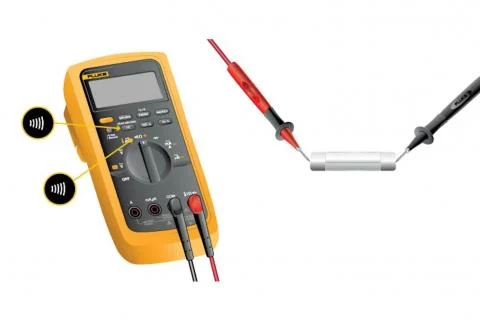
- First insert the black test lead into the COM jack.
- Then insert the red lead into the VΩ jack. When finished, remove the leads in reverse order: red first, then black.
- With the circuit de-energized, connect the test leads across the component being tested. The position of the test leads is arbitrary. Note that the component may need to be isolated from other components in the circuit.
- The digital multimeter (DMM) beeps if a complete path (continuity) is detected. If the circuit is open (the switch is in the OFF position), the DMM will not beep.
- When finished, turn the multimeter OFF to preserve battery life.
Continuity testing overview #
- Continuity is the presence of a complete path for current flow. A circuit is complete when its switch is closed.
- A digital multimeter’s Continuity Test mode can be used to test switches, fuses, electrical connections, conductors, and other components. A good fuse, for example, should have continuity.
- A DMM emits an audible response (a beep) when it detects a complete path.
- The beep, an audible indicator, permits technicians to focus on testing procedures without looking at the multimeter display.
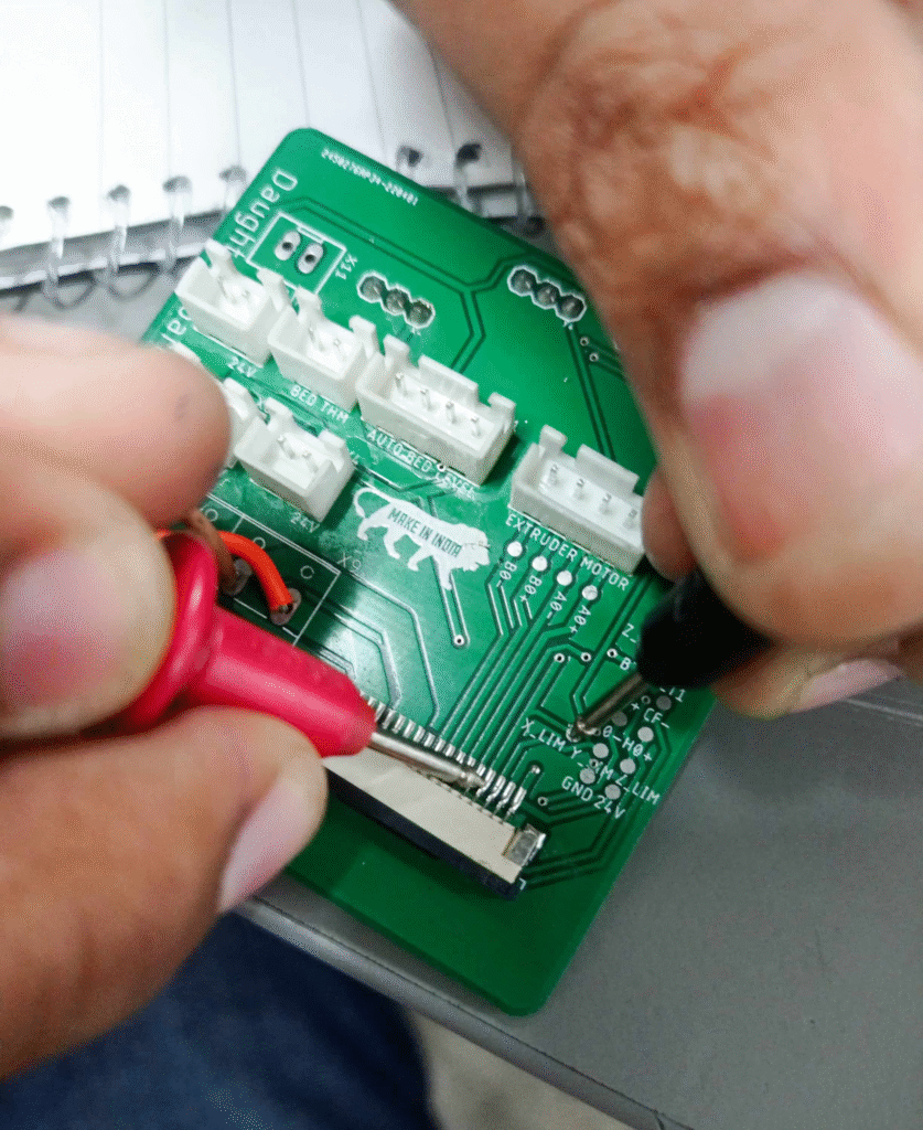
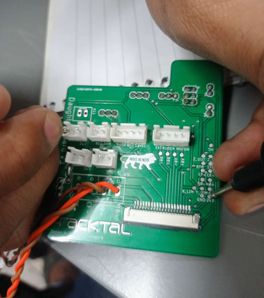
Fracktal printers have custom-made PCBs and use FFC instead of normal wires to reduce the mess by having too many wires. To check connectivity issues, you need to use a multimeter.
Note: Certain components follow a closed-loop circuit. Closed-loop systems will show connectivity even though there is a break in the circuit. So if you are testing for continuity of the closed loop circuit, make sure you remove the end component and make it a open loop (Ex, remove the Limit switch, hot end, thermistor etc incase you need their connectivity )
To check the continuity of the circuit, there are test points on the PCBs.
Step1.
Check the component whose continuity you have to check. (Ex – Limit switch)
Step2.
Find the test point for the component in the first board, considering the Carriage board. (ex, X-axis Limit switch has test point X-LIM)
Step 3.
Find the test point on the other board. Consider Chassys board. Keeping the two multimeter probes on the required test point should give you a beeping sound if there is no problem with the continuity of the circuit. If there is a breakage/Issue with the circuit, the probe will not beep.
Ex: When you keep probing the X limit test point of the carriage board and the X limit test point of the chassis board, it should beep if the connections are fine. If the connection has an issue, the multimeter will not beep.
4. Once an issue is found with the connectivity, you need to check the FFC for breakage or damage.
5. If you are checking connectivity between 2 boards where there is a PCB in between, you need to check connectivity between the individual boards to determine where the connection is faulty.
Ex: If you check connectivity between a point in the carriage board and between the MKS daughter board and find the connectivity to be faulty, you need to check connectivity between the Carriage PCB and Chassis PCB. And then between Chassys PCB and the Daughter board of MKS.
Note: If the connectivity is fine, but still there is no power output at the connecting pin, there is are chance that the board is damaged. To confirm if the board is damaged, you need to check connectivity between the test point and the output pin, like the JST pin or the FFC connector.
Checking connectivity between the FFC connector pin. Normally, these pins get burnt due to various reasons.
Checking the JST pin terminal and test point. Sometimes, due to a loose connection or short circuit, the connectors get burnt.


