
The most important part of the Fractory window is the settings panel on the right. You need to choose the correct settings in this panel to get your desired print quality.
Fractory’s settings panel is divided into two sections. The topmost section is the Printer Settings, and the next section is called Print Setup.
PRINTER SETTINGS
Printer: This is the printer that you selected in the first step. If you have more than one printer, then these can be set up and then selected from this dropdown menu.
Material & Temperature: Quickly select the material and nozzle that your printer is using, and temperatures will be automatically adjusted.
PRINT SETUP
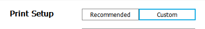
There are two options: Recommended and Custom.
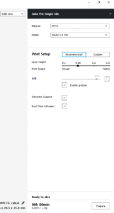
Settings tabs in the Fractory GUI: The recommended print options are calculated based on the settings you input when initially configuring the Fractory slicer for your printer. This option is a great choice when you’re just starting or you just want to see how the software and printer communicate. Options are limited under the Recommended header, but you can quickly adjust quality, infill, plate adhesion, and basic support structures.
Custom: This is where the fun really starts and will enable you to adjust the print settings, from quality through to speed. We’ll look at this section and the options a little later.
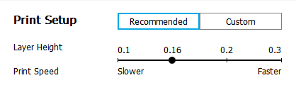
The recommended settings
LAYER HEIGHT
Change Layer Height according to the desired print quality. As we have already discussed, 3D printers print an object by depositing layer after layer of material. The Layer Height slider in Fractory controls the height of each layer. Here, the rule is: the lower the layer height, the better the print quality and vice versa. But note that setting a low value for Layer Height means that the print is going to take proportionally longer to complete. You need to make a trade-off between quality and print speed and pick your own sweet spot. 0.1 mm is a good starting point.
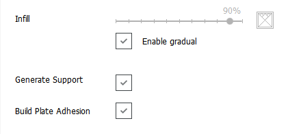
INFILL IN FRACTORY
Change Infill Density to control the sturdiness of the model. The Infill slider controls the quality of the infill. Setting it to 0 % essentially means that you don’t want any infill and want your object to be hollow. Anything in the range of 10% – 40% is known as a light infill. The 50% – 90% range is called a medium infill. Setting the slider to 100% will produce the strongest model. Light is a good starting point.
When the Infill slider is set to above 0%, a checkbox titled Enable Gradual appears. Checking this box will make Fractory gradually increase the amount of infill towards the top of the model. This lets you use a low value for Infill and still get decent top quality. It’s recommended that you check this box when using low values for Infill.
HELPER PARTS IN FRACTORY
These are your support and adhesion settings – controlled by two checkboxes titled Generate Support and Build Plate Adhesion. If this is your first print, then switch both on. As a rule, if your 3D model has plenty of contact with the print platform then switch off Build Plate Adhesion. If your model has no overhang, switch off Generate Support in Fractory’s Helper Settings.
Generate a G-code file with Fractory
The model is now print-ready, and all you need to do is export the file from Fractory. Fractory will now handle everything, converting the 3D STL or OBJ into the G-code file required by the printer.
Save the 3D print file: Click either Save to file, Save to SD, or Desktop on the bottom right of the window.
Estimate of time for 3D print: Fractory will give you a rough estimate on the length of time it will take for your printer to print the piece.
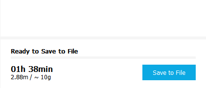
Start the 3D print: If tethered, sit back and wait for the printer to fire up and start printing. If you save to SD, then eject the SD card from your computer and transfer it to your printer. Select print, select the file, and go.
4.
FRACTORY TUTORIAL: MASTER FRACTORY SLICER SETTINGS
What are Fractory’s Custom Settings?
Using the recommended Fractory settings is just the start. Fractory’s standard settings will produce decent prints, but you might often run into some specific issues. For example, you might not like the surface finish of the print. In some cases, the surface might contain a spurious line of excess material, also known as a Z-Seam. Your printer nozzle might be leaking material during travel moves, leaving strands of filaments in places where there should be none. There are plenty of other problems that you might encounter when using the simple settings in Fractory – print speed too slow, the object not durable enough, the bottom surface is warped, etc.
All of these problems can be solved with the help of the Custom settings panel in Fractory. This is why you should be aware of the Custom settings panel in Fractory and know how to change these settings to tackle specific problems and obtain the best possible print quality.
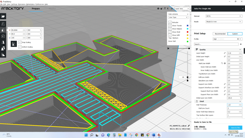
Fractory’s Custom settings can be accessed by clicking on the Custom tab on the Settings panel. This will expose the Custom settings, which is divided into 9 sections – Quality, Shell, Infill, Material, Speed, Cooling, Support, Build Plate Adhesion, and Special Modes. Each section contains a few settings.
Note, however, that the Fractory settings that you see under each section are only a small fraction of the settings that you can actually change. Many settings are not visible by default.
Enabling hidden settings in Fractory
This is what you need to do to expose the Fractory settings that are hidden: Click the Burger icon next to a section header. A window will pop out. This window shows all the Custom settings. There are about 150 different settings here, but don’t worry, you will need to use only a handful of them to solve the most common problems.
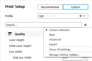
In order to make a hidden setting visible, simply check the checkbox corresponding to that setting and then close the window. From now on, this setting will be visible anytime you access the Custom settings panel.
There are a lot of things to be played with under Custom settings the following sections, we will dive into Fractory’s most important Custom settings and explain how you can use them to improve print quality and solve common 3D printing problems. This is where things get really interesting, so buckle up.
5. FRACTORY TUTORIAL: MASTER FRACTORY SLICER SETTINGS
Control Overall Print Quality in Fractory
This setting is actually a duplicate of the Layer Height slider in the Recommended settings, but we will go through it again – with some pictures this time!
Identical models printed with varying layer height. Notice how thinner layers (right to left) lead to better quality. The Layer Height setting controls the height of each printed layer (in mm) in the Fractory software. Here, the rule is: the smaller the layer height, the better the print quality and vice versa. But note that setting a small value for layer height means that the print is going to take proportionally longer to complete. You need to make a trade-off between quality and print speed and pick your own sweet spot.
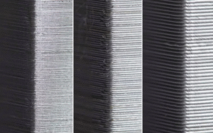
A closer look at the impact of layer height on the surface finish.
6. FRACTORY TUTORIAL: MASTER FRACTORY SLICER SETTINGS
Control Wall/Shell Quality- Affects Surface Finish and Durability
These settings under the heading Shell affect the outside of the print in the Fractory slicer.
Wall Thickness controls the thickness of the outer walls.
The most important setting in this section is called Wall Thickness. The Wall Thickness adjusts the total thickness of the outer walls (but not the top or bottom walls). This value should be an integer multiple of the nozzle size of your printer. For example, if the nozzle size of your printer is 0.35mm and you choose the Wall Thickness to be 3 times that (1.05mm), then the printer will essentially print 3 walls (each wall being 0.35mm thick).
In general, a Wall Thickness of 2 or 3 times the nozzle diameter is sufficient. A higher value will create a sturdier model and decrease the chance of leaks, while a lower value can significantly decrease the print time and filament costs.
With higher wall thickness, there are more print lines.
With lower wall thickness, print lines are fewer.
Horizontal Expansion can correct for shrinkage due to cooling.
All plastics shrink as they cool. Some plastics, like PLA, shrink only a little bit, while others, like Nylon or ABS, shrink a lot. When you are working with precise sizes, shrinkage can be a big frustration, as your model will typically end up being smaller than the measurement of the CAD model. The Horizontal Expansion setting will allow you to adjust the size of your 3D print in the X/Y dimension to compensate for the change in size that happens when the plastic shrinks as it cools.
Horizontal Expansion is one of the Fractory settings that are hidden by default. So you have to enable it first by following the procedure we outlined before. Once enabled, it will appear under the Shell settings.
A positive Horizontal Expansion value will add to the dimensions of your model. You should use a positive value when your printed model is smaller than you expected, as it is most common with shrinkage.
A negative Horizontal Expansion value will reduce the dimensions of your model. Use a negative value when your printed model is larger than expected.
The Z-Seam Alignment setting can prevent a prominent Z-Seam on the 3D model surface.
Sometimes, the printer will leave a mark on the model surface at the start of each layer. When these marks all align, the 3D model will have a prominent spurious line on its outer wall. This line is called a Z-Seam. The Z-Seam Alignment setting lets you choose where in the 3D model surface this line appears or lets you get rid of the line altogether.
The prominent line in the model wall is the Z Seam. You probably want to avoid this artifact. The Z-Seam Alignment setting is also hidden by default. First, enable it so that it appears under the Shell settings in the Fractory software.
Z-SEAM ALIGNMENT CHOICES
There are four choices for the Z-Seam Alignment setting: Shortest, User Specified, Sharpest Corner, and Random.
Shortest is Fractory’s default value. When selected, the Fractory slicer software instructs the printer to start printing a new layer from the endpoint of the previous layer. This often leads to a visible seam, so this choice should usually be avoided.
User Specified lets you specify where exactly on the model surface you want the Z-Seam to appear. When selected, two more settings become available – Z-Seam X and Z-Seam Y. These Fractory settings correspond to the X-Y coordinates of the Z-Seam.
Sharpest Corner instructs the printer to start printing each layer from the sharpest corner on the model surface. A corner, by virtue of being sharp, can cover up a Z-Seam in many cases. However, if your model does not have sharp corners, then this option is not too useful.
Setting Z Seam Alignment to Random will start each layer at a random position. This will eliminate the seam, but will also lengthen the print time as the print head will require additional time to move to a new position between each layer.
The Fill Gaps Between Walls setting prevents gaps in the model surface.
Sometimes when you print thin walls with Fractory 3D, the areas between the inside and the outside of the walls are left unfilled. This might happen when the width of your wall is between a multiple of Fractory’s line width (printer nozzle diameter). Fractory leaves the inside and outside walls unfilled to prevent putting too much plastic into that section of the object, but it also means that gaps can show up in the print. The Fill Gaps Between Walls setting lets you choose how Fractory handles these gaps.
Notice the gaps near the perimeter of the model? Those are the wall gaps we are talking about. The Fill Gaps Between Walls setting is also hidden by default. First, enable it so that it appears under the Shell settings.
There are two choices for this setting: Everywhere and Nowhere. When Nowhere is selected, Fractory will not fill any gaps. When you select Everywhere, Fractory 3D will fill every gap in your print’s walls and will make your model’s outer shell as strong as possible.
The Alternate Extra Walls setting lets you add strength to the outer walls without putting too much burden on print speed. eed
Earlier, we discussed how you can make a model stronger and more durable by adding more walls (i.e., increasing wall thickness to be a higher multiple of the nozzle diameter). However, the thicker the wall, the more time it takes to print it. Fractory offers a compromise between wall thickness and print speed via the Alternate Extra Walls setting. When enabled, the Fractory software will add one extra interior shell to every other layer. For example, if your print is set for two nozzle diameters, Alternate Extra Walls will add an extra nozzle diameter on every odd-numbered layer.
To enable this setting, first make it visible so that it appears under the Shell settings. Then simply check the checkbox corresponding to this setting.
The Wall Speed setting lets you improve surface finish
If you are still not satisfied with the surface finish of the model, here’s one more thing you can do. There’s a hidden setting called Wall Speed under the Speed section (and not under the Shell section!). This setting controls the speed at which the printer head moves while printing the walls.
There are two separate settings for inner wall speed and outer wall speed. The default outer wall speed is 30 mm/s. Setting the outer wall speed a little lower than the default (try reducing in steps of 10 mm/s) can improve the surface finish of the model. Of course, decreasing the outer wall speed means that you are signing up for longer print times as well – so keep this in mind.
7. FRACTORY TUTORIAL: MASTER FRACTORY SLICER SETTINGS
Control Infill Pattern – Affects Model Strength, Material Consumed, and Print Time
By default, the Fractory slicer prints a grid-shaped infill, printing in one diagonal direction per layer. This provides reasonable strength without eating up too much material. It is also one of the fastest patterns in terms of print time. Fractory‘s standard infill pattern should be fine for most common applications.
In some special applications, though, the default pattern might not be best. In such cases, Fractory offers a range of infill patterns to choose from.
Fractory 3D infill patterns. There are more infill patterns available than shown in the picture. To change the Fractory infill pattern, enable the Infill Pattern hidden setting, and it will appear under the Infill section. You have a choice of 13 different patterns. Some of the important patterns are:
Grid: A grid-shaped infill, with lines in both diagonal directions on each layer.
Lines: Creates a grid-shaped infill, printing in one diagonal direction per layer.
Triangles: Creates a triangular-shaped infill pattern.
Cubic: A 3D infill of tilted cubes.
Tetrahedral: A 3D infill of pyramid shapes.
Concentric: The infill prints from the outside towards the center of the model. This way, infill lines won’t be visible through the walls of the print.
Concentric 3D: The infill prints from the outside towards the center of the model, with an incline over the entire print.
Zig Zag: A grid-shaped infill, printing continuously in one diagonal direction.
How to choose infill patterns?
The major factors you need to take into account when choosing the infill pattern in the Fractory slicer are:
Is the part going to be used for mechanical purposes?
Does the model have a large capping surface?
If the part is not going to be used as a mechanical part, but rather for aesthetic purposes, then you might be able to get away with having no infill at all. However, if the same 3D model has a large capping surface, then the capping surface will require some support in order to be printed. In such cases, your best infill choice is Concentric. This uses minimal material and is the fastest to print. At the same time, it provides enough support for the top surface.
If you want the model to have reasonable strength even if you are not going to use it for mechanical purposes, then the best option is to select a 2D pattern such as Grid, Lines, or Triangles. Lines provide the least amount of strength but do not consume a lot of material and print fast. Grid consumes more material, is slower, but provides more strength. Triangles offer great strength and high lateral loads. Use this infill when you need good wall strength or longer, slender structures.
If the model is going to be used for mechanical purposes, the best option is to go for a 3D infill pattern such as Cubic or Tetrahedral. With these patterns in Fractory, you’ll get excellent internal support and near isotropic mechanical properties.
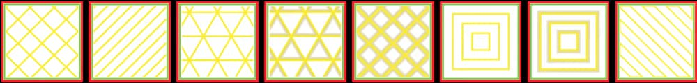
Various infill patterns.
8. FRACTORY TUTORIAL: MASTER FRACTORY SLICER SETTINGS
Control Overall Print Speed – Affects Print Time and Print Quality
3D printing is not instantaneous like document printing. Printing something simple, like a standard coffee mug, can take several hours. The long print times can be very frustrating at times. Therefore, the Fractory slicer software offers a setting to control the overall print speed (simply called Print Speed) and several other separate settings to control the print speed of special structures like walls, infill, support, etc.
As a rule, the specialized settings in Fractory software always override the overall speed (Print Speed) setting. We will talk about the specialized speed settings when we discuss the corresponding special structures (we have already discussed the Wall Speed setting). But in this section, we want to focus on the overall speed setting and its effects.
Fractory’s Print Speed setting controls print time and also affects print quality
Fractory’s Print Speed setting can be found under the Speed section of the Custom settings. This setting refers to the speed at which the printer head moves during the print. The default value is 60 mm/s.
To reduce print time, simply increase this speed. However, you should take note that increasing the print speed affects other things as well, and you should make necessary adjustments accordingly.
When the printer head travels faster, the filament might not have sufficient time to melt as it comes out of the nozzle. This usually results in brittle models. You can usually solve this problem by increasing the extruder temperature so that the plastic can melt properly.
Faster printer speed implies that the printer head is going to jerk and vibrate more vigorously. The model might show ripples in the surface as a result. Therefore, faster print speeds usually come at the cost of compromising quality.
Effect of print speed on print quality
FINDING THE OPTIMUM SPEED IN THE FRACTORY SLICER
To find the optimum speed in Fractory, it’s usually recommended that you experiment by going up in steps of 5 mm/s. This means, try 65 mm/s, and check if you like the result. If you do, go up again to 70 mm/s. At some point, the print quality will become unacceptable. You can then choose a Print Speed in Fractory 3D that is 5 mm/s below this point.
If you find that you can’t increase speed without degrading the quality, another idea is to just increase the Infill Speed setting. This is a hidden setting, so you have to make it visible first. This setting controls the speed at which the Infill is printed, without affecting the print speed of other parts of the model. Since the infill is invisible, the quality of the infill doesn’t matter as much. But it reduces print time all the same.
In some situations, you might actually need to decrease Print Speed. If you are printing highly detailed models, a lower print speed will help in reproducing details more accurately. There are also some filaments like PET+ or Flex PLA, which usually require lower print speed settings in the 3D slicer.
To slow down the print speed, simply lower the value of the Print Speed setting. Filament manufacturers will often have a “suggested print speed” for their specialty filaments. For highly detailed models, start by lowering the print speed by 10mm/s, then adjust it up or down in increments of 5mm/s as needed.
9. FRACTORY TUTORIAL: MASTER FRACTORY SLICER SETTINGS
Prevent Excessive Cooling by Using the Fan Speed Setting
Extruded filament remains malleable until it cools. Therefore, many 3D printers use cooling fans to speed up this process and harden the material as it is being laid down. A good cooling system also prevents distorting the last layer as a new (and hot) layer is being laid down.
Fractory enables cooling by default, except for the first layer. The first layer is skipped, as cooling it would reduce the print’s ability to adhere to the build platform. All other layers are printed with cooling turned on.
However, when you have cooling turned on, the nozzle might fail to reach the temperature required to melt the plastic. This is a case of excessive cooling. When it happens, your printer will simply stop and display an error message saying that the nozzle couldn’t reach the required temperature.
Fractory 3D offers a way to solve the excessive cooling problem via the Fan Speed setting. This is a hidden setting under the Cooling section. As usual, you should make it visible in your 3D slicer first so that it appears under the Cooling section.
The value of this setting is set as the percentage of the fan’s maximum speed. If you need to adjust the setting in Fractory, start by modifying the value to 80%. Be aware that for values below 20%, the fans may not receive enough power to spin at all.
10. FRACTORY TUTORIAL: MASTER FRACTORY SLICER SETTINGS
Prevent Distortion of Small Layers by Using the Minimum Layer Time Setting
For very small prints, a layer might print so fast that the fans do not have enough time to cool it before the next layer starts printing. When this happens, the unfortunate small layer warps due to the heat of the next layer. The result is a mess.
Here’s what your print will look like if the smaller layers are getting distorted because of insufficient cooling. The Minimum Layer Time setting in the Fractory slicer can help solve this problem. This is a hidden setting under the Cooling section. Using it, you can give the fan more time to cool down these very small layers. The value of this setting is the minimum time for a layer to print. For very small layers, Fractory will slow down the print speed so that the layer takes at least the minimum time to finish printing.
The default value for this setting is 5 seconds. If you are running into distorted small layers, start by increasing it to 10 seconds, then continue to make adjustments in 5-second increments as needed.
11. FRACTORY TUTORIAL: MASTER FRACTORY SLICER SETTINGS
Disable Cooling for Filaments that Don’t Need it
Some materials, like Nylon, Polycarbonate, and PET+, need to be printed in still air. These materials shrink a lot when cooled. If cooling is enabled while printing with these materials, the model will warp and distort in unexpected ways.
You need to turn off cooling in Fractory when printing with these materials. Simply look for the Enable Print Cooling setting under the Cooling section and uncheck the checkbox. Fractory will turn off cooling when you do that.
12. FRACTORY TUTORIAL: MASTER FRACTORY SLICER SETTINGS
Prevent Warping by Using Build Plate Adhesion and Other Fractory Settings
When plastics are printed, they first expand slightly but contract as they cool down. If the material contracts too much, this causes the print to detach from the build plate and bend upwards. This phenomenon is called warping in 3D printing slang. Some materials shrink more than others (e.g., ABS, PET+, PC, or Nylon have a higher shrinkage than PLA), which means there’s a larger chance of warping when using them.
Warping causes the lower layers to lift and warp. Fractory offers some settings that help prevent warping. The most important of these is the Build Plate Adhesion Type setting, found under the Build Plate Adhesion section. There are three options for this setting: Skirt, Brim, and Raft.
Skirt is the default option in Fractory. It is a line around the print on the first layer that just helps to prime the extruder.
If you get significant warping, you should consider changing to the other options, Brim or Raft.
When you choose Brim, Fractory places a single-layer-thick, flat area around your object, which resists the pulling forces as the print cools. As the brim is only a single layer thick, it’s easy to remove once the print is finished.
For some materials or models, a brim might not be enough to prevent warping. In these instances, using Raft in the Fractory settings is advisable. A raft adds a thick grid between the model and the build plate, ensuring that the heat is distributed equally. It is particularly useful when the bottom of a model is not completely flat, or when printing with industrial materials.
The Build Plate Adhesion section is not the only one that can help prevent warping. Here are some other Fractory settings that can help.
Other ways to prevent warping in Fractory 3D
A thicker first layer often makes adhesion easier. You can make the first layer thicker by changing the Initial Layer Height setting. This is a hidden setting under the Quality section in the Factory slicer. Make sure you change the value to a number higher than what you chose as Layer Height.
It is important not to set the initial layer speed too high, as the material may attach to the nozzle and get dragged around with it, instead of remaining fixed to the build plate. To slow down the speed for the first layer, first, make the setting called Initial Layer Speed under the Speed section visible. Then set the speed lower than the default value.
There’s another setting called Number of Slower Layers in Fractory, which can help with better build plate adhesion. This setting will slow down the printing of the bottom layers and defines the number of layers it will take the printer to reach the set print speed. The speed, based on the initial layer speed and print speed, will linearly increase over the number of layers specified in the Number of Slow Layers setting. A higher value will decrease the chance of your print warping, but this setting can also increase your print time significantly.
As we discussed before, the print head fans are usually turned off (fan speed = 0) for the first print layer, to ensure optimum build plate adhesion. Fractory offers another setting called Regular Fan Speed At Height, which turns on the fan gradually, from no fan for the first layer to maximum power at the specific height. In this sense, this setting is equivalent to Number of Slower Layers, but for cooling. It’s a hidden setting, so you will have to make it visible. Try a value slightly higher than the default, and it should improve plate adhesion.
Take care of hardware issues first.
Take note that warping can happen for many reasons, such as wrong calibration, tilted build plate, or insufficiently heated build plate. Some of these issues cannot be addressed within the scope of the Fractory slicer, so you should ensure that you have fixed these issues before you try messing with the Fractory settings.
13. FRACTORY TUTORIAL: MASTER FRACTORY SLICER SETTINGS
Prevent Pillowing by Using a Combination of Shell, Cooling, and Quality Settings
Sometimes, the top surface of the print is not completely closed and shows bumps. This is called pillowing in 3D printing slang. This problem often stems from incorrect Shell, Cooling, or Quality settings. Here’s how you can solve it by tweaking the Fractory slicer settings.
Pillowing leads to an imperfect top surfacePillowing can be best addressed by changing the Top/Bottom Thickness hidden setting under the Shell section. Like any other hidden setting in Fractory 3D, you need to enable it before it appears under the Shell section.
To create a smooth top surface, it’s important to use a thick enough top. When the top is too thin, you get a surface with holes in it. To fix this, simply increase the Top Thickness. The recommended thickness is six times the layer height. So if your layer height is 0.1mm, then the Top Thickness should be 0.6mm or more.
But the Top Thickness is not the only factor when it comes to pillowing. Sometimes, too little cooling might also be at the root of this issue. If the plastic does not cool properly, it may hang down a bit or curl up at the places where it crosses the infill lines. This means that an uneven surface is created for the next layer that must be placed on top of it, leading to bumps on the top surface.
Therefore, if increasing the Top Thickness does not solve the problem, try increasing the Fan Speed under the Cooling section. It seems that especially thinner layers have the tendency to curl up. Therefore, it could help to increase the layer height.
14. FRACTORY TUTORIAL: MASTER FRACTORY SLICER SETTINGS
Prevent Stringing by Using a Combination of Materials and Print Settings
Stringing is yet another common problem. Sometimes, you will find strands of plastic in your print where there shouldn’t be any. This typically happens when the extruder leaks plastic as it moves from one point to another during a non-extruding phase.
Stringing in actionTo get rid of stringing in Fractory or any 3D slicer, the most obvious course of action is to enable retraction. Retraction essentially means that the filament is pulled back a little bit by the feeder when the print head performs long travel moves. This effectively stops the leaking of filaments. To enable retraction, look for the Enable Retraction checkbox under the Material section. Make sure the box is checked (it should be checked by default).
However, enabling this setting is often not enough to stop stringing completely, and you might have to tweak the print temperature and speed to completely get rid of this problem.
Tweaking temperature and speed to get rid of stringing in Fractory
Print temperature plays a big role when it comes to leaking filament. If the temperature is very high, the filament will be more liquid and prone to dripping through the nozzle. Therefore, reducing the print temperature goes a long way in reducing stringing. You can find the Printing Temperature setting under the Material section. It’s hard to say which temperature to use exactly. It depends a lot on the filament. Try reducing the temperature in steps of 10 degrees in the Fractory software until you get the best results.
Keep in mind that when you reduce the temperature, there is a chance that your material will start under-extruding. Earlier, we discussed the connection between temperature and print speed and how they need to be adjusted together for the best results. So when you lower the temperature, make sure you reduce the print speed accordingly.
It might also help to increase the travel speed under the Speed section. This way, the print head will travel a bit faster so that the material has less time to drip from the nozzle while traveling. Travel speed of 200 mm/s should be fine for most prints.
15. FRACTORY TUTORIAL: MASTER FRACTORY SLICER SETTINGS
Control Support Structures – Affects the Success of Prints with Overhangs
Many 3D models have overhangs. These 3D models require additional support structures to print successfully. Fractory can generate these support structures automatically in most cases. When the print job completes, the support structures can be removed by breaking them off manually from the model.
When using support structures, three issues come up most frequently:
Is the support structure correctly placed and strong enough to provide the required stability during the print job?
Is the support structure easy to remove afterward?
Does the support structure deteriorate the surface finish of the overhanging parts?
Fractory 3D offers a host of support structure-related settings under the Support section of the Custom Settings. Using these settings, it is possible to create support structures that provide the necessary stability, are not too hard to remove, and do not affect the surface finish of the model. Let’s dive in and see how to make adjustments.
Turn on auto-generated support structures for unstable models in Fractory
How do you figure out if your model needs additional support?
Fractory 3D makes this easy. Once you have imported your model into the Fractory 3D slicer and positioned it on the virtual build plate, look out for sections colored in red. Those are the parts where Fractory has detected instability. Note that it is possible that you will not see unsupported areas until you rotate the camera view.
If you see red on the bottom of the part, where the model touches the build plate, you don’t have to worry about this area being unsupported. The build plate will take care of this problem. Small red areas at the top of holes or between two structures are called bridges, and Fractory will handle them automatically, too.
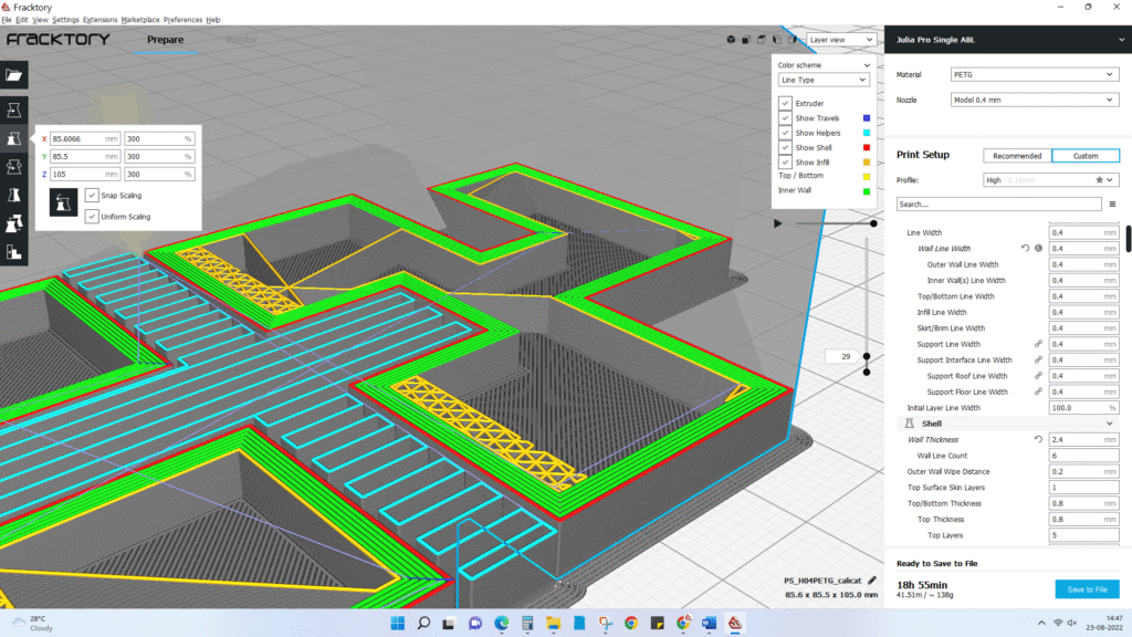
If there are other parts highlighted in red, then you need to start worrying. To begin with, you need to enable the auto-generated support structures to ensure that those red parts can be printed successfully. To do this, simply check the Generate Support checkbox under the Support section in Fractory 3D.
So you have now enabled the auto-generated support structure, but probably didn’t see anything change in the model view. That’s because Fractory does not show the support structures in the default Solid view. To see the support structures that were generated, change the view to Layer View. Support material (lines and volume) will be displayed in teal. Move the layer slider up and down to see where Cure 3D added the support structures to the 3D model.
Control placement of support structures
When you enable support structure, a setting called Placement automatically appears under the Support section. The Placement setting lets you coarsely control the positioning of the support structure. There are two options: Everywhere and Touching Buildplate. Everywhere is selected by default.
When Everywhere is selected, Fractory 3D attempts to build structures wherever they are necessary. This means you not only have support structures that are erected on the build plate, but also support structures that use part of the model as its base. This is the reasonable option in most cases, as this ensures that all unstable areas will have the necessary support.
Two types of support structure placement in Fractory: Everywhere and Touching BuildplateHowever, if Everywhere is selected for very complicated models, the model might end up being completely encased by support material. If you don’t want this, simply change the Placement setting to Touching Buildplate. This will create support structures underneath overhanging sections of the model, only between the build plate and the model.
The Enable Support Roof can improve the surface finish of the overhang, but at a cost.
Since a model’s overhang is always printed on top of support structures, you don’t always get the best surface finish for these parts. The Enable Support Roof hidden setting can help with that.
A support roof is a dense skin at the top of the support structure, which does not compromise the surface finish of the overhangs too much. When you enable this setting in Fractory 3D using the checkbox, you will get a better finish quality. But this improvement comes at a cost, as this option makes the support structures harder to remove than usual. Use this option only if the surface finish of the overhanging part is critical to the function of the finished part.
Prevent support structures from damaging the model’s outer walls by using the Support X/Y Distance setting.
Sometimes, the support structures are built too close to the model’s outer wall and leave marks on the model’s outer surface. You can prevent this from happening by using the Support X/Y Distance hidden setting under the Support section.
The Support X/Y Distance setting in Fractory essentially controls the minimum allowed distance between the model’s vertical walls and a support structure in the X-Y plane. If your support structure is damaging the walls or sticking to them, you can increase the value by increments of 0.2mm until the walls come out smooth. However, please ensure that no small overhangs are sticking out of the outer walls that will go unsupported if you put a little bit of distance between the support and the walls. If such small overhangs exist, you might even have to decrease the X/Y distance instead of increasing it. Otherwise, you will get a failed print.
The Z Distance setting can help make the support structures easier to remove
For the support material to break away cleanly without pulling the model layers apart, the connection between the support material needs to be made weaker than the connection between the layers of the model. Fractory creates this weaker connection by leaving a space between the top and bottom of the support structure and the model, and this space is known as Z-Distance.
You can make the support structures easier to detach by controlling the Z-Distance hidden settings under the Support section. The default value for this setting is the same as the layer height. So if your layer height is 0.1mm, the default Z Distance will be 0.1mm too.
If your support material is difficult to break away from your model, increase this value in increments of your layer height until it comes away cleanly. Fractory can either add support to any given layer or not add support. Unfortunately, there are no “half layers of support.” So if a 0.2mm Z Distance setting for a print with a layer height of 0.1mm is too much, and the Z Distance of 0.1mm is not enough, you’re out of Z Distance options.
Select the proper support structure for the right balance between strength and ease of removal.
Fractory generates support material in one of seven patterns. You can change the pattern by using a hidden setting called Support Pattern under the Settings section.
Support patterns in Fractory most cases, the default pattern, Zig Zag, will generate the best balance between strength and ease of removal. The other pattern options are Triangles, Lines, Grid, Concentric, Concentric 3D, and Cross. If you are unhappy with the default pattern, you can experiment with the other options. Each of them will give you a different balance between strength and ease of removal.
16. FRACTORY TUTORIAL: MASTER FRACTORY SLICER SETTINGS
Special Modes in Fractory 3D
The Fractory slicing software has some special modes that let you print in unconventional ways. They can come in handy when you have special needs like
You want to print a model at a fraction of the time for a normal print
You want to print a model with a non-manifold design
The Spiralize Outer Contour mode lets you print super fast by sacrificing durability
In the Spiralize Outer Contour mode, the printer simply prints the walls in one continuous. The Spiralize Outer Contour special mode is a hidden setting under the Special Modes section in Fractory’s settings. When you enable it using the corresponding checkbox, Fractory will print a hollow model instead of a solid model. The extruder will trace a continuous path that spirals upwards along the walls of the model, printing a solid base and a one nozzle-width thick wall. It will not print any infills or support.
This mode is very different from standard layering in 3D printing since the extruder moves in the Z direction at all times, instead of stepping up only when a layer has been completely printed. Since the extruder moves continuously and prints only the walls, this reduces the print time to a fraction of normal. It also enables you to save a lot of materials (no infills).
On the downside, models made using the Spiralize Outer Contour mode usually are not durable due to the lack of infill.
If you want to print in this mode, keep the following warnings and settings in mind:
Spiralize Outer Contour doesn’t work if your model has overhangs exceeding 45 degrees.
Flat areas parallel to the build platform cannot be printed in this mode.
When this mode is selected, Fractory will still respect the layer height, print speed, and other basic settings in Fractory. This means that you will need to select the Layer Height and Line Width. Set Wall Thickness to the same value as your Line Width, change Wall Line Count to 1, set Top Layers to 0, and set the Infill to 0%.
Fractory’s Surface Mode lets you print non-manifold designs
If you want to print non-manifold designs or orphaned geometry, Fractory offers a special mode for that! It’s called Surface Mode, and it is available as a hidden setting under the Special Modes section.
When you make the setting visible, you will have three options: Normal, Surface, and Both. When you select Normal, Fractory tries to print the object normally. When you select Surface, Fractory only prints the X-Y walls and makes them one nozzle width thick. This lets you print walls that are not connected to any solid volume. When you select Both, Fractory prints solid parts of the model normally, and prints only the walls for non-manifold areas or orphaned parts.
17. FRACTORY TUTORIAL: MASTER FRACTORY SLICER SETTINGS
Conclusion
So that’s it for this looong Fractory 3D tutorial. We hope you enjoyed it.
If you have followed everything and can successfully apply the right Custom settings to the right problems, the print quality you are getting out of your printer should improve by leaps and bounds. If you indeed experiment a lot with Fractory 3D after reading this article, we would love to hear about your experience – fails, successes, and everything in the middle.
While we have tried to cover the most important settings in this tutorial, we left many not-so-commonly used settings out. Fractory 3D has more than 100 hidden Custom settings – we use only about 40 in our day-to-day printing. We hope that once you start experimenting with the commonly used Fractory settings, you will dare to go beyond and try out the other hidden settings. This entire process of optimizing settings to squeeze every bit of quality out of the printer is challenging, fun, and addictive!


