













Design for 3D Printing
Most parts that fail were lost at the CAD stage, not on the printer. These are the rules we check every quoted file against, on wall thickness, holes, overhangs, spans and orientation, with the real numbers for the materials we run.
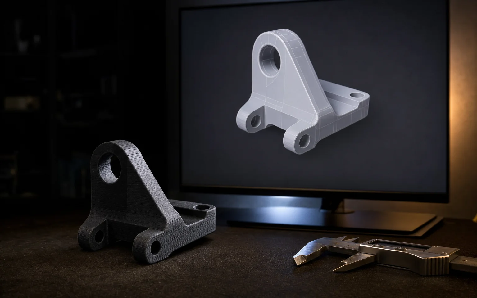
Where Printed Parts Actually Fail
Layer direction
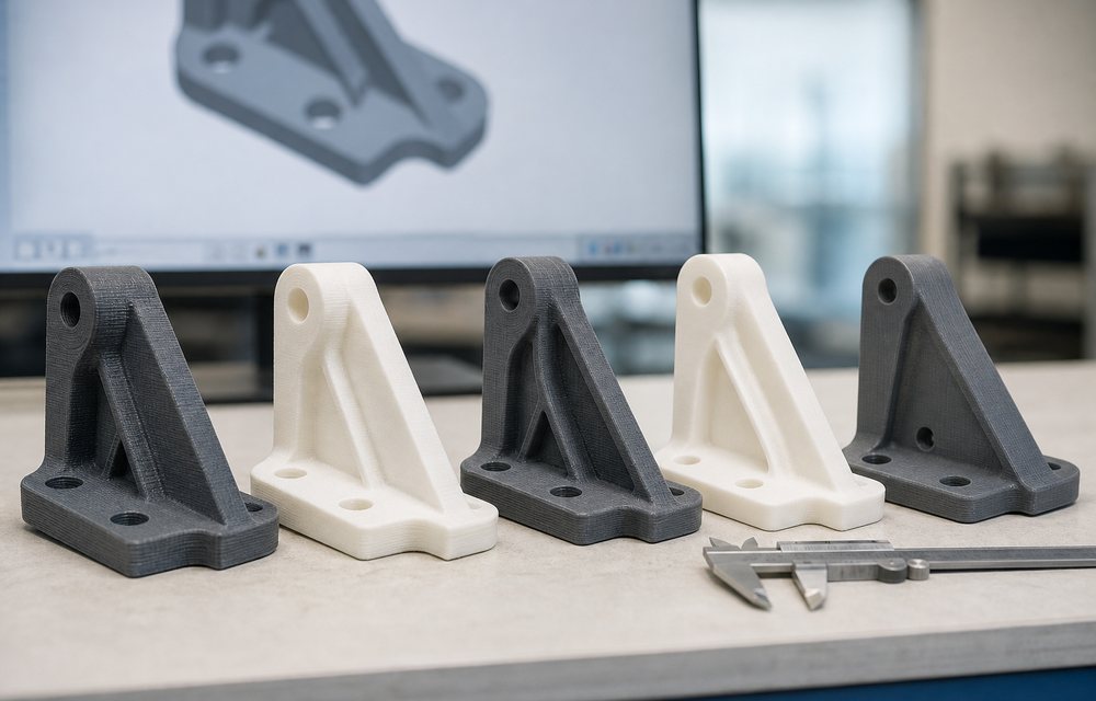
An FDM part is strong along its layers and weak across them. A bracket printed flat and the same bracket printed upright are not the same part. Tell us which way the load goes and orientation is chosen for it, or move to SLS or MJF, which are near-isotropic.
Walls that are too thin
Below the minimum wall a feature either does not appear or appears without strength. The floor is set by the process and the material, not by the CAD.
Overhangs and bridges
Past the overhang angle a surface needs support, and support leaves marks. Redesigning a 60° overhang to 45° is usually cheaper than finishing the scar it would leave.
Design Limits by Material
| PLA | PETG | ABS | Nylon PA12 | CF Nylon | |
|---|---|---|---|---|---|
| Minimum wall thickness | 0.8 mm | 0.8 mm | 1.0 mm | 1.2 mm | 1.5 mm |
| Minimum hole diameter | 1.0 mm | 1.2 mm | 1.5 mm | 1.5 mm | 2.0 mm |
| Overhang limit | 55 ° from vertical | 50 ° from vertical | 45 ° from vertical | 45 ° from vertical | 40 ° from vertical |
| Unsupported bridge | 30 mm | 20 mm | 15 mm | 15 mm | 10 mm |
Five Things Worth Doing Every Time
Fillet the inside corners
A sharp internal corner is a stress riser and a crack start. A small radius costs nothing in CAD and buys real strength.
Design holes slightly undersize
Printed holes tend to come out a little tight. If the fit matters, print undersize and drill or ream to size, or tell us the fit and we will allow for it.
Give threads a real anchor
Printed threads in fine pitches rarely last. A heat-set insert or a tapped boss in a thicker wall is the durable answer.
Avoid large flat first layers
A big flat face on the bed is where warping shows first, especially in ABS. Break it up or orient the part so it is not the footprint.
Send STEP, not just STL
STEP keeps exact curves and dimensions. An STL exported coarse arrives faceted, and we cannot recover what the export threw away.
Say what it has to survive
Load, heat, chemicals, UV, cosmetic or not. Every decision above changes with the answer, and it is the one thing a CAD file cannot tell us.
Design Questions
What is the minimum wall thickness for 3D printing?
How steep an overhang can I print without support?
What tolerance can I expect?
Which way should the part be oriented?
Do you check my file before printing?
The Data Behind These Rules
- Every material, one tableMeasured properties for all 12
- PLA vs ABS vs PETGThe three most-used filaments compared
- FDM vs SLA vs SLSAccuracy and minimum wall by process
- Bed adhesionWhy first layers fail, and the fixes
- Quality assuranceHow parts are inspected before they ship
- Get your file checkedA DFM review comes with every quote
Have an Engineer Look at It
Send the file and what the part has to do. The DFM check comes with the quote, including the changes we would make and why.