








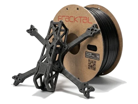



Carbon Fiber Nylon
(CF-PA) Filament
Short-fiber reinforced PA12 composite for high-strength structural FDM printing.

Quick Reference
- Material properties
- Carbon Fiber Nylon (CF-PA)
- Engineering composite
- Polyamide 12 (PA12)
- Short chopped carbon fibre
- FDM / FFF
- 82 MPa
- 145 °C
- 1.1 g/cm³
- 35 MPa
- 1.1 %
- 260–280 °C
- ≥0.6 mm (0.8 mm recommended)
- Hardened steel (≥0.4 mm)
Material Property Profile
Values scored 0–10 from measured mechanical data and print process behaviour. Select a material above to compare properties.
Key Properties
Engineering values with the context that decides whether CF-PA is the right choice for a load-bearing part.




Machine Requirements
Can your printer handle this? These are the hard thresholds for reliable CF-PA output.
| Requirement | Minimum Spec | Recommended |
|---|---|---|
| Nozzle Temperature | 260 °C | 265–280 °C |
| Bed Temperature | 80 °C (heated mandatory) | 100–110 °C |
| Nozzle Material | Hardened steel | Hardened steel (carbide optional) |
| Enclosure | Strongly recommended | Fully enclosed + temp-controlled |
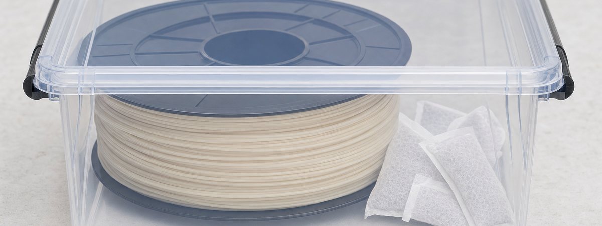
| Drying | 70 °C / 6 hr before print | 80 °C / 8 hr; re-dry if open >4 hr |
| Bed Surface | PEI / Garolite | Garolite (G10) |
| Nozzle Diameter | 0.6 mm minimum | 0.8 mm recommended — finer nozzles clog on short fibres |
| Retraction | ≤1 mm (direct drive) | Direct drive preferred |
CF-PA is an engineering-grade material. Standard FDM printers with PTFE hot-end liners cannot reliably print above 240 °C. Check that your machine has an all-metal hot-end before ordering. Moisture first, surface second — Nylon and CF-PA bed adhesion.
Applications by Industry
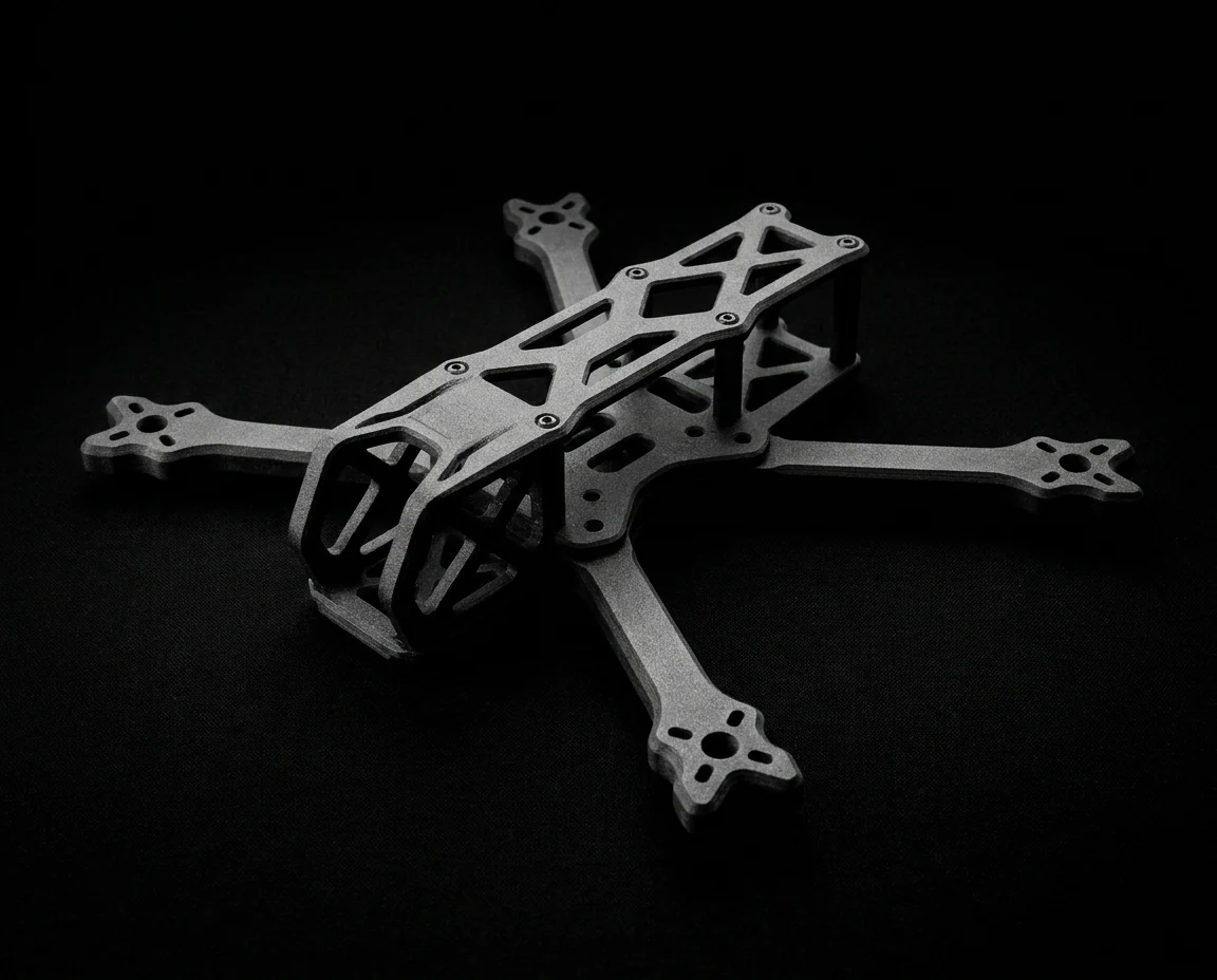
Aerospace & Defence
- Jigs & fixtures
- Structural brackets
- Tooling inserts

Automotive
- Under-hood components
- Sensor housings
- Intake manifolds

Industrial Tooling
- End-of-arm tooling
- Robotic grippers
- Drill guides

Electronics
- EMI-shielding housings (conductive CF variants)
- Structural enclosures

Sports & Performance
- Bicycle components
- Equipment frames
- Protective gear

R&D / Prototyping
- Functional prototypes validated in the final operating environment
Tensile Strength Across the Range (MPa)
Heat Deflection vs Tensile Strength
Available Materials
When to Use CF-PA, and When Not To
Use CF-PA when
- Part operates above 80 °C continuously.
- High stiffness-to-weight ratio is required (e.g. EOAT, structural brackets).
- Dimensional stability over temperature cycles is critical.
- Part will be machined or drilled after printing.
- You need to replace metal in low-to-medium load applications.
Avoid CF-PA when
- Part requires high impact / ductile failure — use unfilled Nylon or TPU instead.
- Surface aesthetics are primary — CF-PA has a matte, slightly rough finish.
- Your machine lacks an all-metal hot-end.
- Part contacts food, drinking water, or medical fluids (not certified).
- You need tight tolerances without post-machining (moisture variability ±0.3 %).
DfAM Tips for CF-PA
Design rules that turn a printable part into a structural one.

Wall thickness ≥ 1.5 mm
CF fibre reinforcement needs a minimum of 3 perimeters to align correctly. Thinner walls print but lose their structural benefit.

Min. hole diameter: 2 mm
Fibre loading stiffens the melt flow around small internal features. Design holes at ≥2 mm diameter for clean, accurate printing without closing over.

Avoid sharp internal corners
Stress concentrations amplify at 90° interior corners in stiff composites. Use fillets of ≥1 mm radius.

Post-anneal for best results
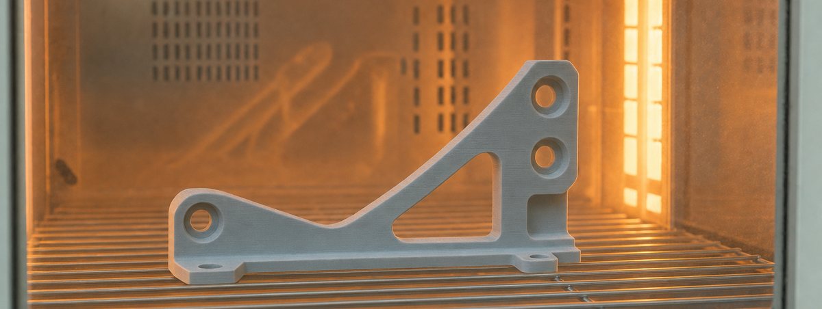
90 minutes at 80 °C in an oven reduces residual stress by ~40%. It also improves interlayer bond strength.

Budget shrinkage in tight-fit assemblies
CF-PA parts shrink 0.2–0.5% depending on geometry and infill density. Add clearance on mating features rather than machining to nominal.

Clearance ≥ 0.5 mm on moving parts
Reinforced fibre limits elastic give at joints. Keep at least 0.5 mm gap between moving or connecting features to avoid binding after cooling.

Max self-supporting angle: 40° from vertical
CF-PA walls print clean up to 40° from vertical without support. Beyond that, add supports or reorient the part to avoid sagging and layer tearing.

Max horizontal bridge: 10 mm
CF-PA filament doesn’t stretch like unreinforced nylon, so bridging capability is reduced. Keep unsupported horizontal spans at 10 mm or less, or add supports for longer gaps.
Printers Compatible with CF-PA
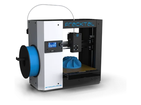
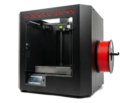
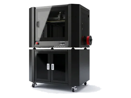
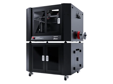
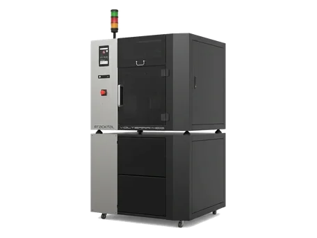
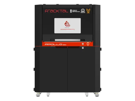
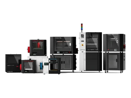
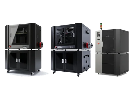
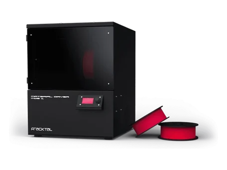
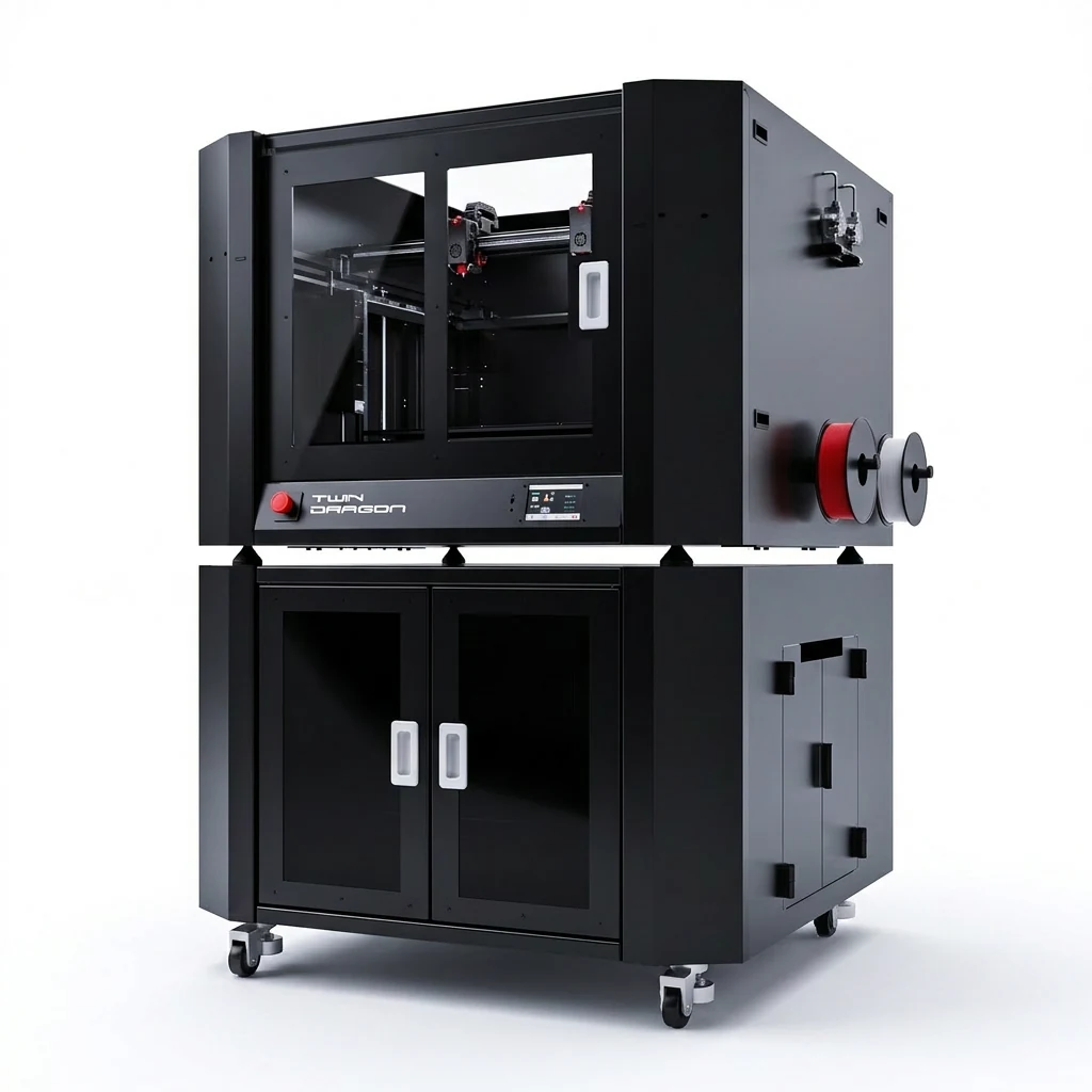
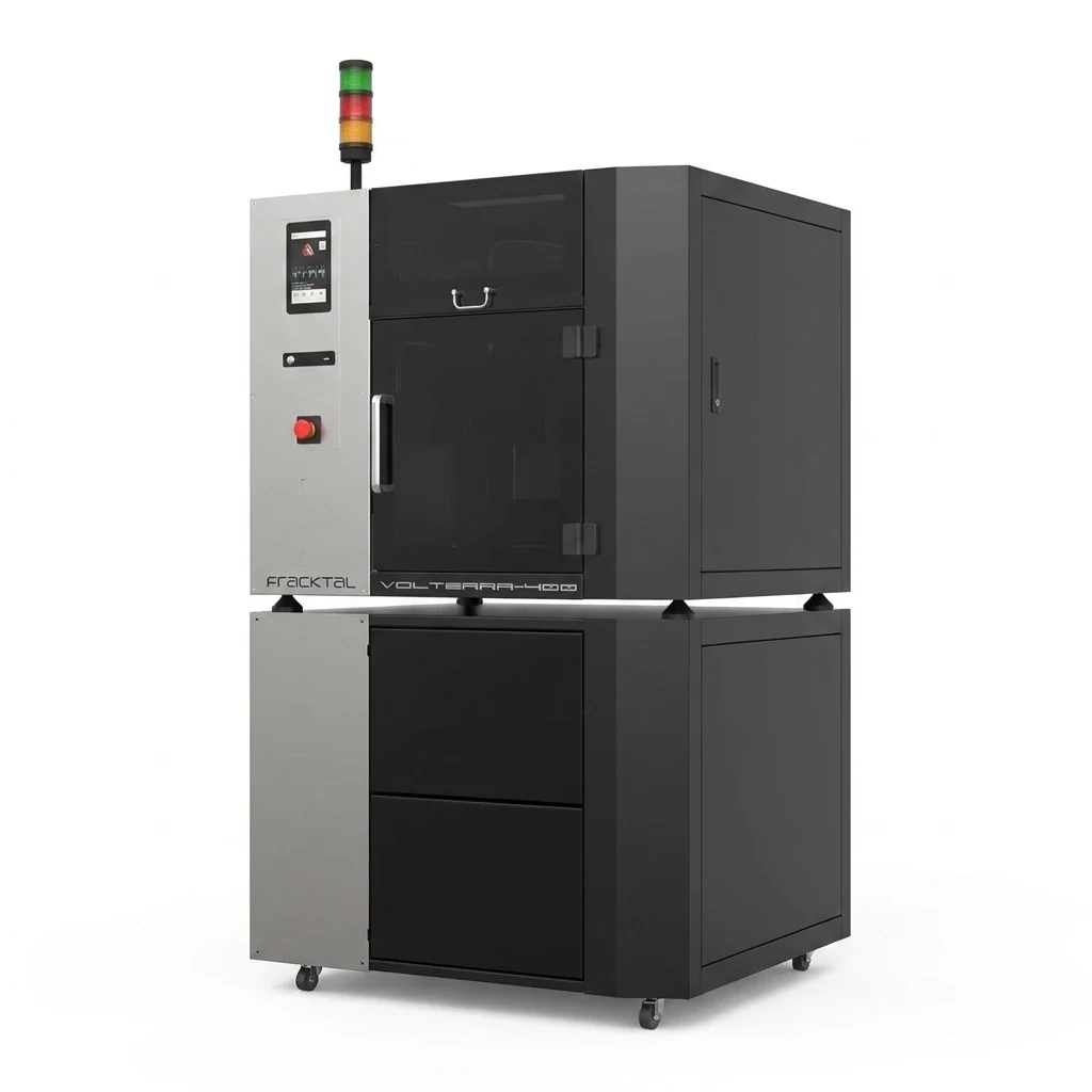
CF-PA requires an all-metal hot-end, an enclosed chamber, and direct-drive extrusion. These Fracktal machines meet every requirement out of the box.


Ready to print in CF-PA?
Talk specs, tolerances and lead time with our applications engineers.