









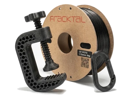



Carbon Fiber PET-G
(CF-PETG) Filament
Short-carbon-fiber reinforced PETG for stiff, dimensionally stable structural parts where chemical resistance matters.

Quick Reference
- Material properties
- Engineering Composite
- Polyethylene Terephthalate Glycol (PETG)
- Short chopped carbon fibre (10–15% wt)
- 58 MPa
- 80 °C
- 1.32 g/cm³
- Low — dry 65 °C / 4 h if stored unsealed
- 245–260 °C
- ≥ 0.4 mm
- Hardened steel (mandatory)
- 75–90 °C
- Recommended
- Sand, drill, tap; carbon dust — wear a mask
Material Property Profile
Values scored 0–10 from measured mechanical data and print process behaviour. Select a material above to compare properties.
Key Properties
Stiffness is what the carbon buys. Read that row first, then check the nozzle you own.




Machine Requirements
One row here is a hard stop: a brass nozzle will not survive carbon fibre.
| Requirement | Minimum Spec | Recommended |
|---|---|---|
| Nozzle Temperature | 240 °C | 245–260 °C |
| Bed Temperature | 70 °C | 75–90 °C |
| Enclosure | Passive | Recommended |
| Nozzle Material | Hardened steel | Hardened steel 0.4 mm+ |
| Cooling Fan | 25 % | 50 % |
| Retraction | 3 mm | 4–5 mm @ 40 mm/s |
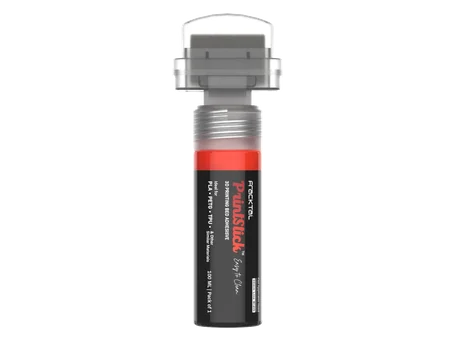
Hardened steel nozzle is mandatory. Carbon fibre will abrade a brass nozzle within minutes of printing, causing diameter growth, stringing, and dimension drift. Never use brass with CF-PETG. Same release problem as PET-G, stiffer — protecting a PEI sheet.
Applications by Industry

Tooling / Jigs
- Assembly jigs & fixtures
- Go/no-go gauges
- Welding locators

Drone / Robotics
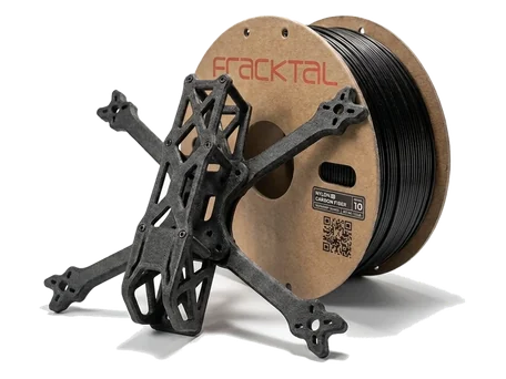
- UAV frames & arms
- Robot chassis plates
- Camera mounts

Automotive
- Interior mounting brackets
- Sensor housings
- Panel clips

R&D / Prototyping
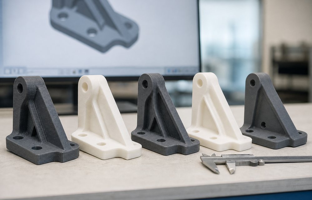
- Reinforced structural prototypes
- Stiffness-critical test parts
- Lightweight mechanical parts
Tensile Strength Across the Range (MPa)
Heat Deflection vs Tensile Strength
Available Materials
When to Use CF-PETG, and When Not To
Use CF-PETG when
- High stiffness-to-weight ratio is the design requirement
- Chemical resistance needed alongside structural performance
- Dimensional stability under thermal cycling is critical
- Matte surface texture is acceptable or desirable
- You have a hardened steel nozzle
Avoid CF-PETG when
- Brass nozzle only — will wear rapidly (use unfilled PETG instead)
- Parts needing smooth polished finish (surface is matte and textured)
- Very long slender spans — impact strength is lower than unfilled PETG
- Food contact applications
DfAM Tips for CF-PETG
Carbon fibre changes what the material will forgive, starting with the nozzle.

Wall Thickness ≥ 1.2 mm (3+ perimeters)
Fibre alignment benefit only appears at 3+ perimeters. Below that, you lose most of the stiffness advantage.

Min Hole Diameter: 1.5 mm
CF-PETG has very low shrinkage but fibre bunching near small holes can reduce accuracy. Add 0.1 mm bore clearance.

Max Overhang: 45°
Carbon fibre does not improve overhang, so use supports beyond 45°. Keep unsupported spans under 30 mm.

Hardened Steel Nozzle Required
Carbon fibres abrade brass nozzles in minutes. Use hardened steel (or ruby) and replace at first sign of wear.
Printers Compatible with CF-PETG
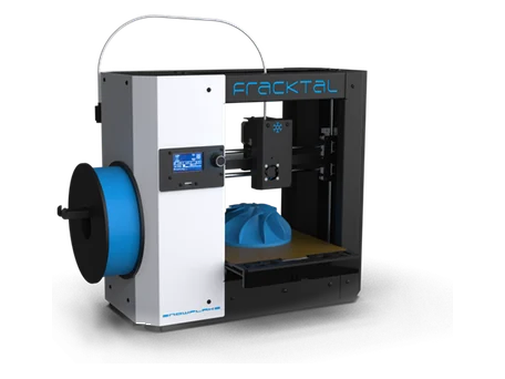
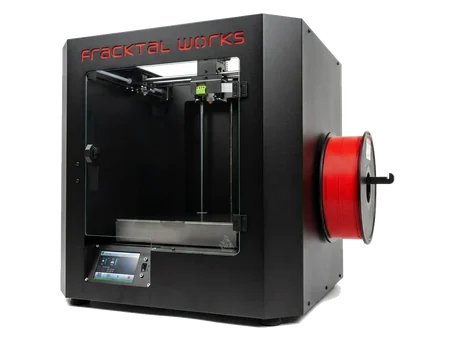
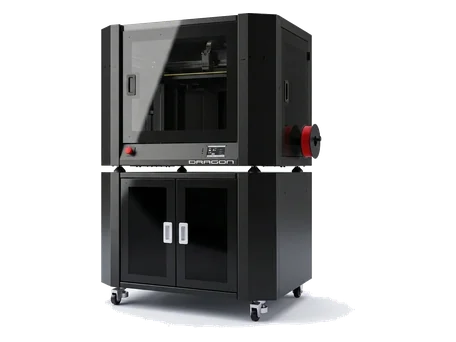
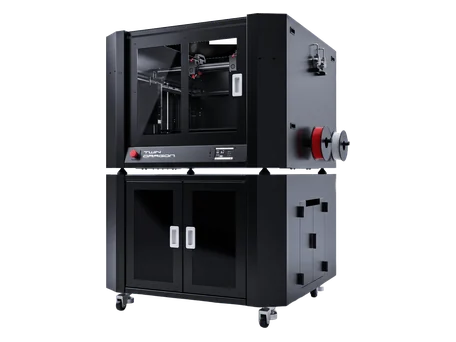
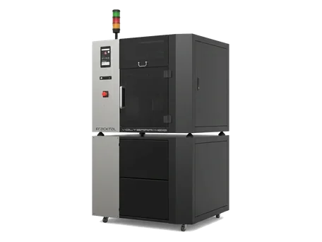
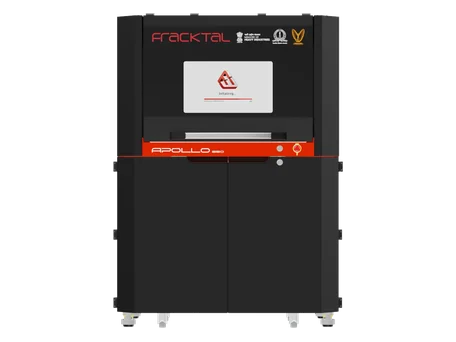
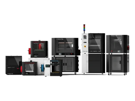
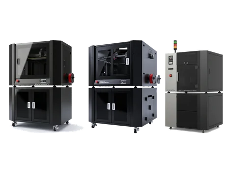
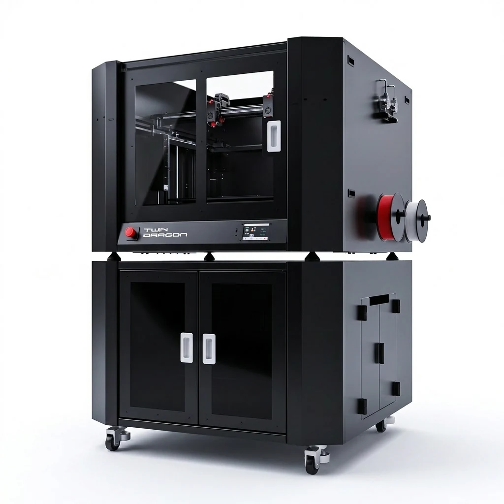
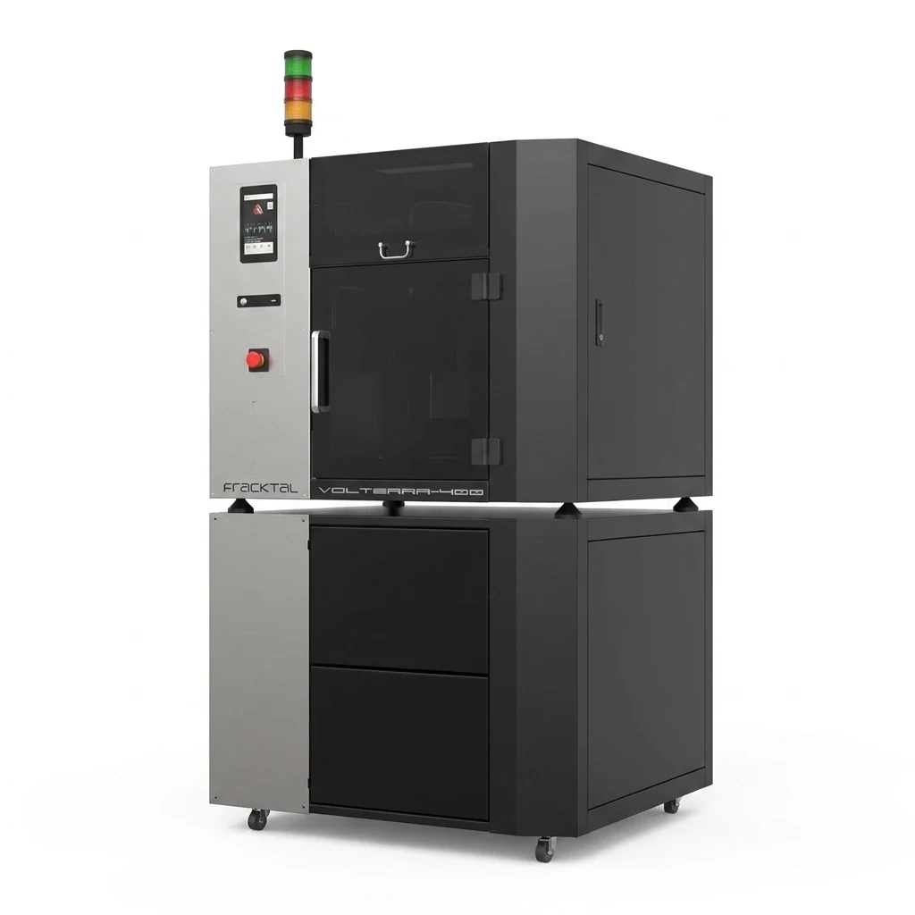
CF-PETG requires an all-metal hot-end with a hardened steel nozzle and reaches up to 260 °C. Dragon, Twin Dragon, Julia, and Volterra all meet these requirements.


Ready to print in CF-PETG?
Fracktal CF-PETG ships in available in 500 g and 1 kg spools.