









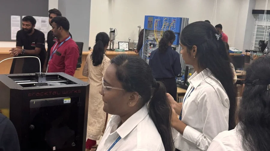

3D Printing in Engineering: From Concept to Functional Prototype

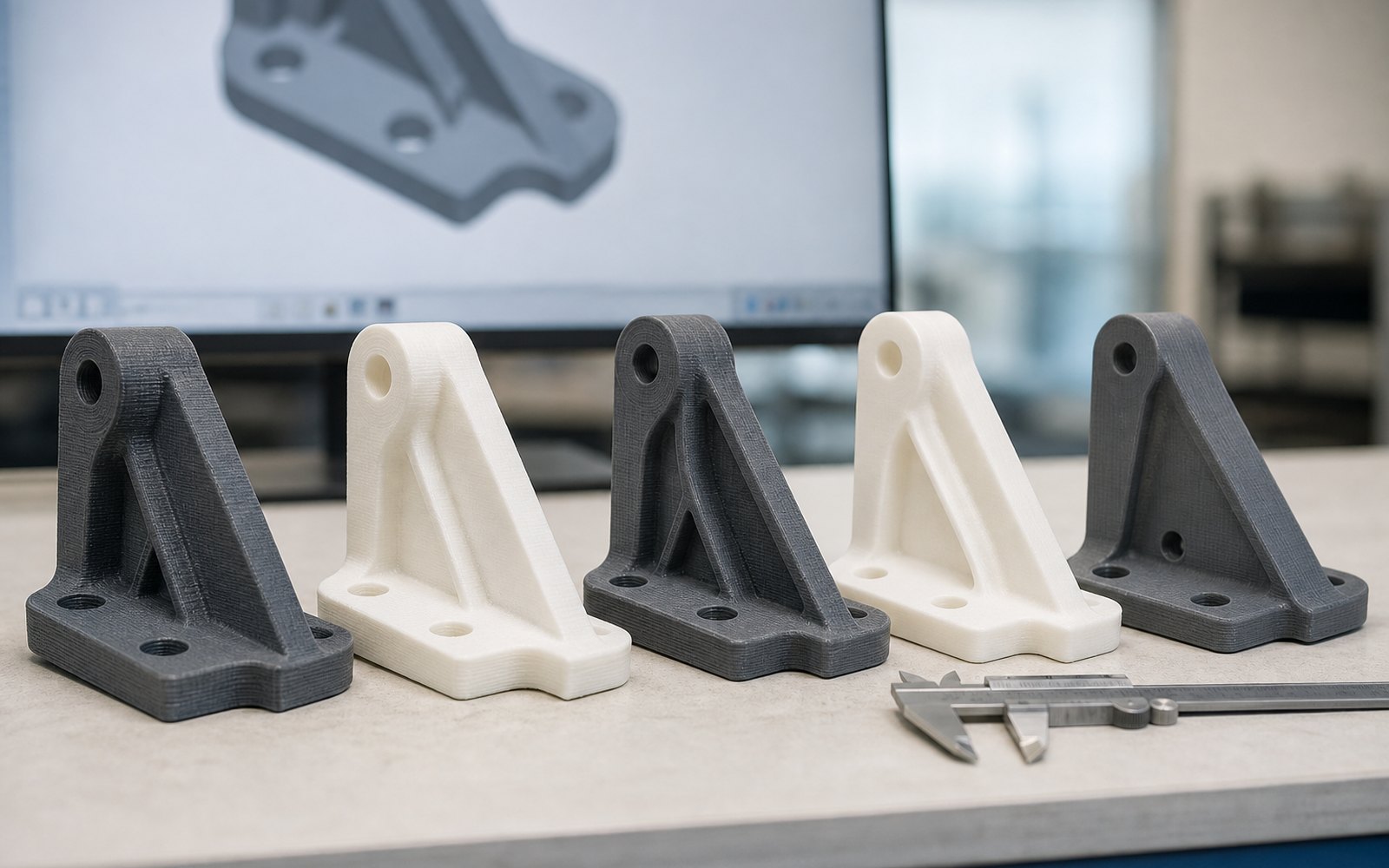
Every product goes through the same ladder: a sketch, a shape you can hold, a version that works, a version that survives testing, and finally the thing you ship. 3D printing does not shorten the ladder. What it does is let a small team climb it in days instead of months, without waiting for a supplier at every rung.
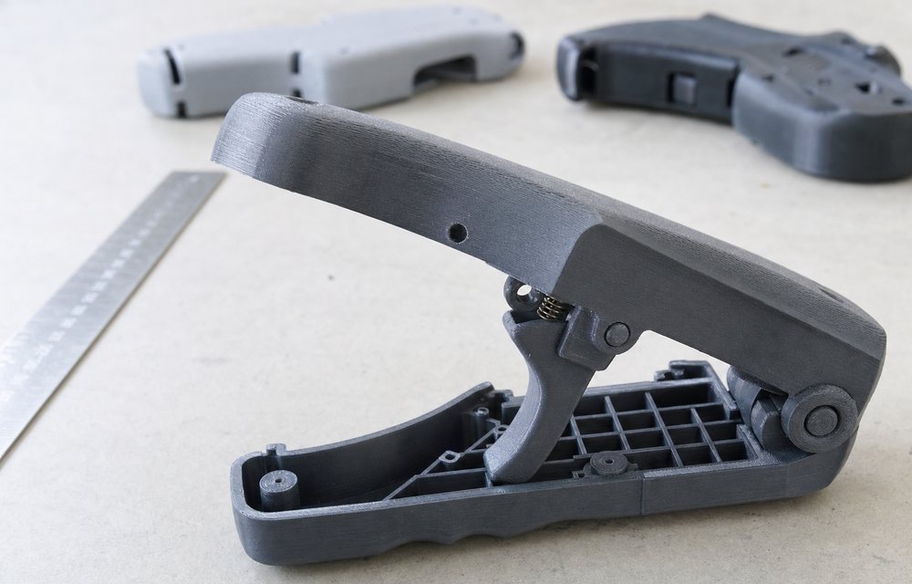
This is how we see engineering teams use it, and where each step tends to go wrong.
Rung one: concept models
The first print of a new design is a check on proportion and feel. Does the handle sit in the hand? Is the housing bigger than the drawing made it look? Is the button where a thumb lands?
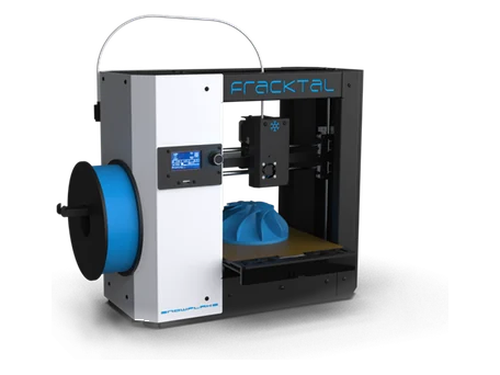
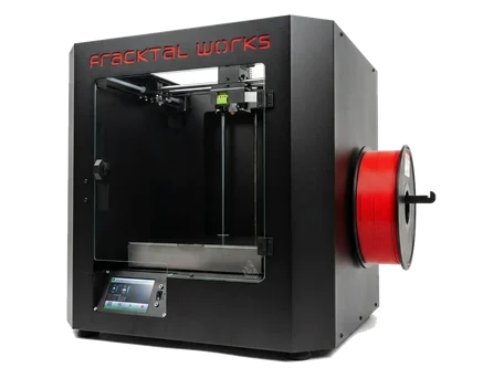
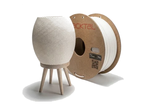
Speed matters more than material here. PLA on a desktop machine, printed at a coarse layer height, gives an answer in a few hours for a few rupees of filament. The mistake at this stage is finishing the part. Nobody needs a sanded concept model; they need the next three versions.
Rung two: looks-like prototypes
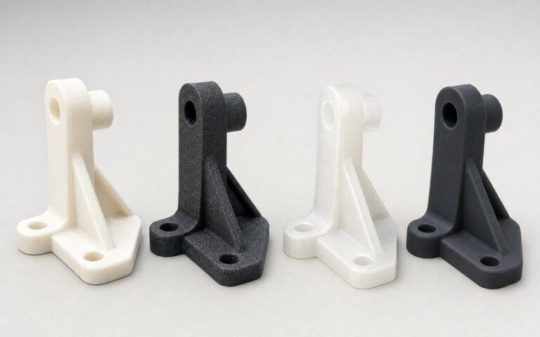
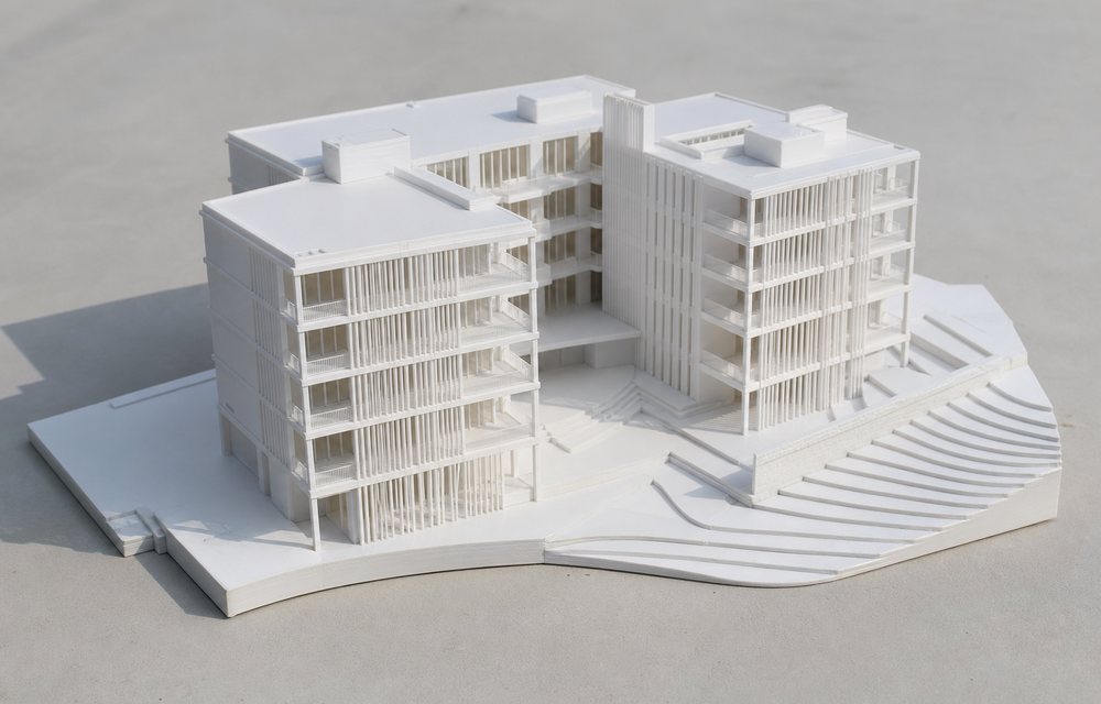
A looks-like model is for stakeholders: the customer, the investor, the marketing photograph. Surface finish now matters, colour matters, and the part is usually assembled from several pieces.
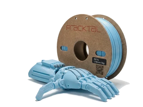
PLA and PETG both take primer and paint well. Print orientation decides how much sanding you do, so put the visible faces upward or vertical and hide the support scars on surfaces nobody sees. Split large parts along natural seams, and design the joints in: a lip and a recess hold alignment far better than glue on a flat edge.
Rung three: works-like prototypes
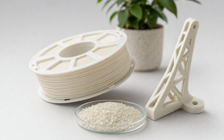
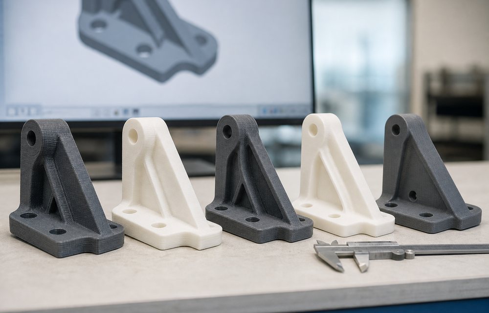
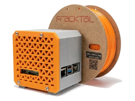
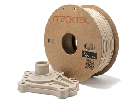
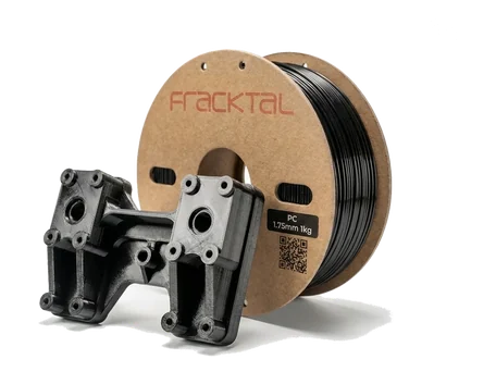
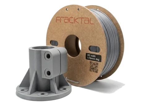
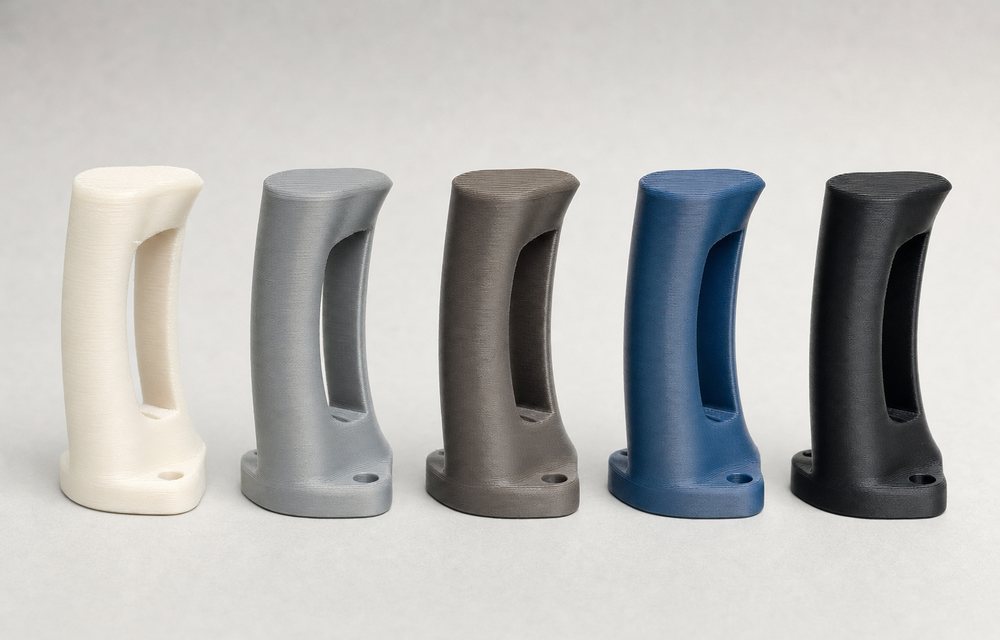
This is where material choice starts to decide the result. A snap-fit that works in PETG will crack in PLA. A housing that holds a warm motor will soften in PLA and be fine in ABS or ASA. A hinge that flexes ten thousand times needs nylon, and a bracket that carries real load wants carbon-fibre nylon or polycarbonate.
The useful discipline is to prototype in the material family you intend to manufacture in, or the closest printable relative of it. A works-like part in the wrong polymer tells you about the polymer, not about the design.
Three design rules save the most reprints:
- Wall thickness. Keep walls at or above 1.2 mm, and above 2 mm where a fastener bites. Thin walls print, then fail in the hand.
- Clearances. Mating parts need 0.2 to 0.3 mm of clearance on FDM, more for a sliding fit. Holes print undersize; drill or ream them if the fit is critical.
- Orientation against load. In fused filament fabrication a layer boundary is the weak plane. Orient the part so the main load runs along the layers, not across them, and add a fillet wherever a sharp corner meets a load path.
We keep a fuller list on our design for 3D printing page.
Rung four: test fixtures and rigs
The part everyone forgets to print is the one that tests the other parts. Fixtures that hold a prototype in a tensile tester, jigs that locate a sensor repeatably, cradles that keep a PCB still while it is probed: these are cheap in FDM and expensive from a machine shop, and they are where in-house printing pays for itself quietly. Our jigs and fixtures page goes into the design of them.
When to leave the desktop
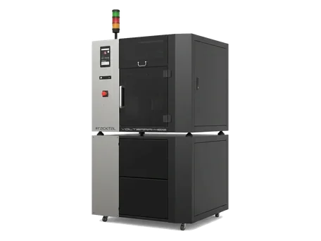
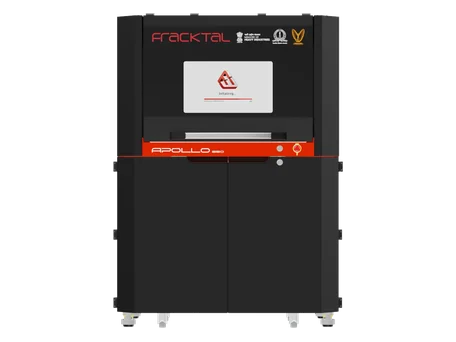
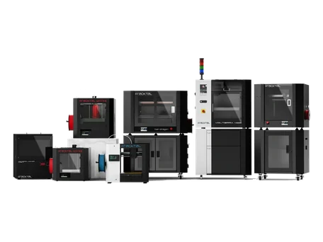
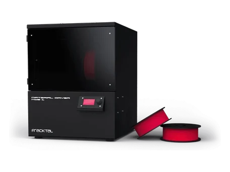
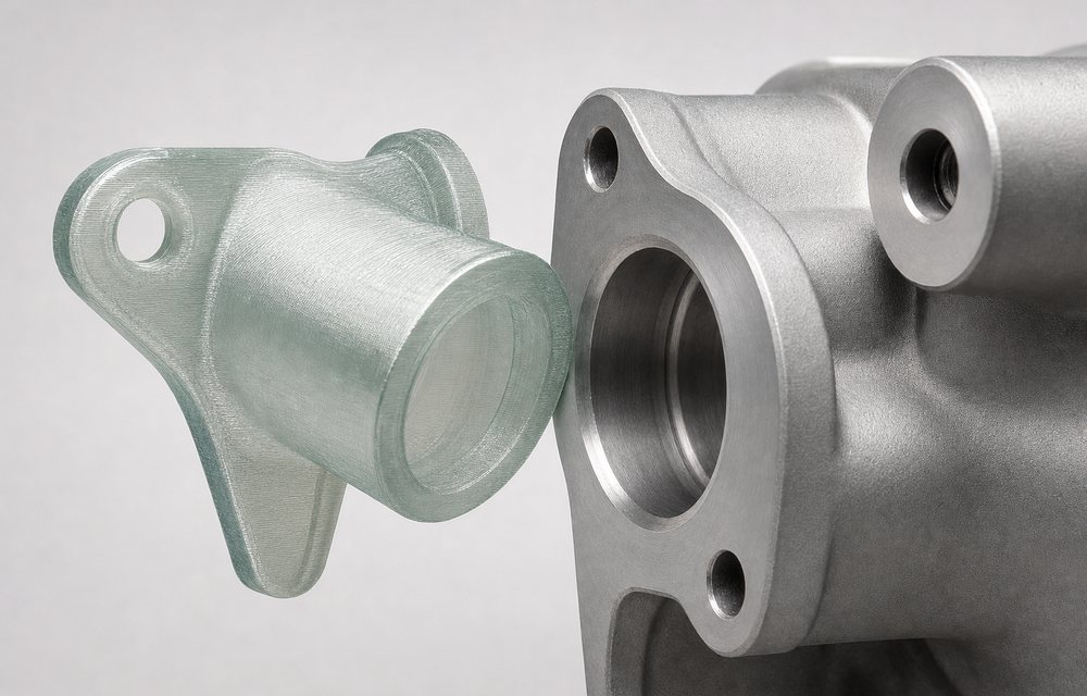
Desktop FDM covers most of the ladder. It stops being the right tool in three cases: when the part is bigger than the build volume and splitting it would compromise the test; when the material needs a heated chamber to print without warping; and when you need twenty of something with a finish that does not show layers.
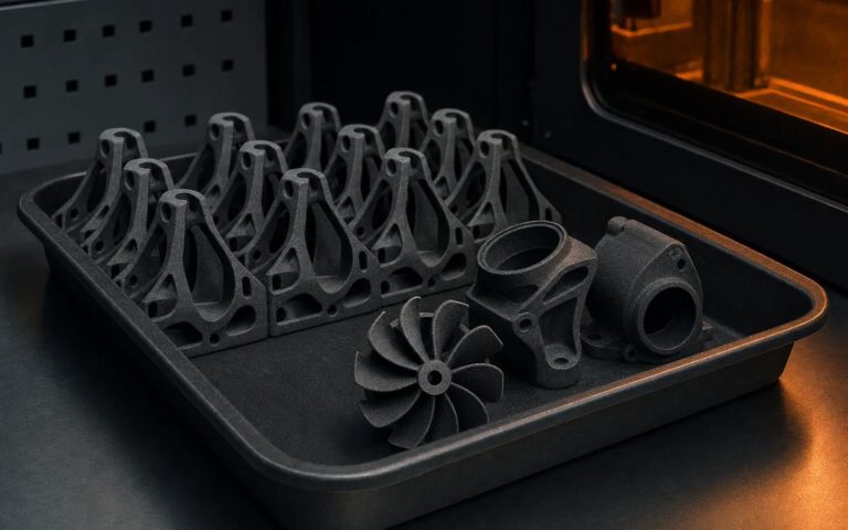
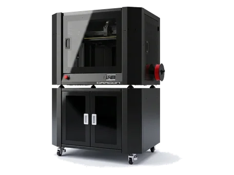
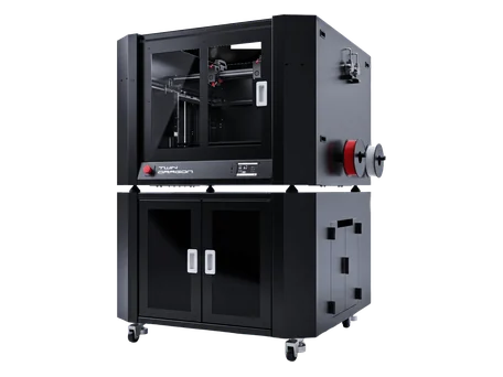
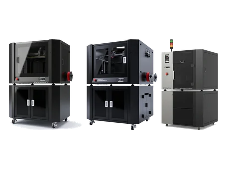
The first two are a case for an industrial FDM machine such as the Twin Dragon, which prints up to 600 × 600 × 400 mm in a 90 °C chamber. The third is a case for SLS or MJF, where nylon parts come out of a powder bed with no supports and a consistent surface, and a batch of twenty costs little more per part than a batch of two. Our process comparison lays out the trade-offs.
Owning the loop
The teams that move fastest are not the ones with the most machines. They are the ones where the engineer who designed the part also prints it, looks at the failure, and changes the file the same afternoon. A desktop machine on the engineering floor, a bench next to it, and a habit of printing before arguing: that is most of what “rapid prototyping” actually means.
When a part is ready to leave the desk, whether for a heated-chamber material, a powder-bed process or a batch, send it through the quote page. An engineer checks the geometry before you pay for anything.