











3D Printing in Robotics: Grippers, Mounts and Housings

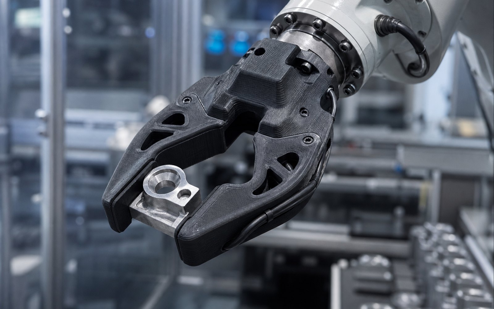
3D printing in robotics is not about printing robots. It is about the parts of a robot that are different on every machine: the fingers that touch the product, the bracket that holds a camera at exactly the right angle, the housing around a controller that nobody makes in a quantity of four. Robots are built in small numbers and changed constantly, and those two facts are the whole case for printing.
This is where printed parts go on a robot, what they are made of, and what changes when you need fifty of them instead of one.
Where printed parts live on a robot
Walk down an arm from the base and the printed parts cluster at the end of it. The links and joints are cast or machined and shared across every unit the manufacturer sells. Everything that adapts the arm to a particular job is specific to that job, and that is what gets printed.
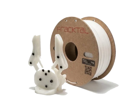
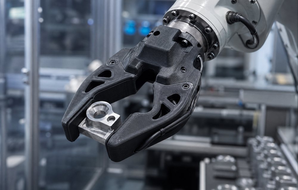
- Gripper fingers and end-effectors. The single most printed part in robotics. Fingers shaped to the product they pick, suction-cup plates with the holes exactly where the part needs them, tool changers and adapter flanges.
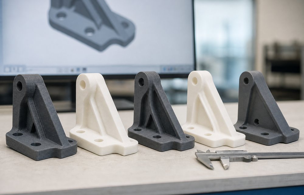
- Sensor and camera mounts. A vision system works when the camera is rigid, at the right height, and out of the way. A printed bracket gets all three in one iteration.
- Cable management and covers. Guides, clips, drag-chain adapters and protective covers that stop cables catching on the world.
- Housings. Enclosures for controllers, drivers, batteries and custom electronics on mobile robots and cobots.
- Wheels, hubs and chassis parts on autonomous mobile robots and research platforms, where a design changes with every field trial.
- Every link of a prototype. Before a new arm or a new leg is machined, the whole thing is printed and moved, to find the collisions and the cable routes the CAD hid.
Materials by job
The material is decided by what the part does, not by what the printer happens to have loaded.
- PLA for proof-of-motion prints: checking a mechanism moves, a bracket clears, a hand fits. Cheap and fast, not for service.
- PETG for covers, guides and light brackets that need a little toughness.
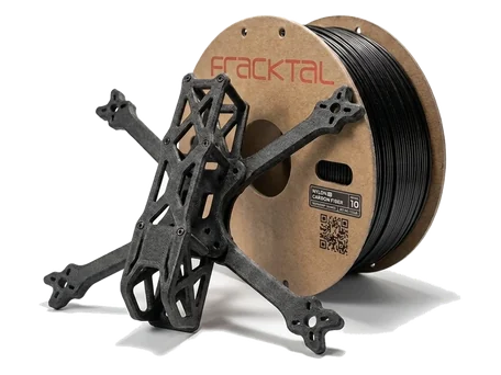
- Carbon-fibre nylon for fingers and brackets that carry load. Stiff, dimensionally stable, and light enough to matter at the wrist, where every gram slows the cycle.
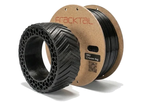
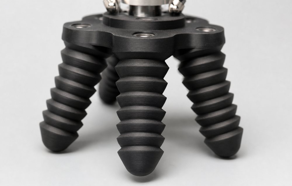
- TPU for compliant fingers, bumpers, feet and pads that grip without marking the product.
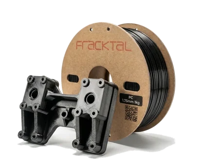
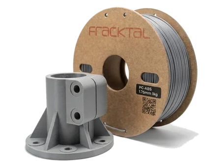
- Polycarbonate and PC-ABS for housings near motors and drives, where heat and impact both matter.
- Nylon 12 by SLS when the part has internal channels, living hinges, or needs to be made twenty at a time with consistent strength in every direction.
The gripper: the part that changes every time
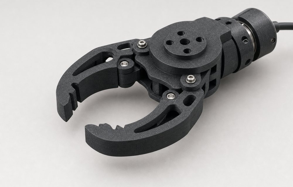
A gripper finger is the clearest example of why robotics and printing fit. The product changes, so the finger changes. A finger machined from aluminium takes a week and costs enough that people keep using the old one. A printed finger is designed in the morning, printed overnight and on the robot the next day, and if it drops the part, the second version follows the day after.
Three things make printed fingers work in service:
- Conformal shape. Print the negative of the product into the finger face. A finger that cradles a bottle needs less clamping force than one that pinches it, and less force means a lighter gripper and a faster arm.
- Compliance where it helps. A TPU pad, or a thin flexing section printed into a rigid finger, absorbs the tolerance between where the part is and where the robot thinks it is.
- Mass at the wrist. Every gram on the end-effector is a gram the arm accelerates and decelerates thousands of times a shift. A carbon-fibre nylon finger at a third of the mass of the aluminium one lets the same arm run faster or carry more payload.
Design rules that keep printed parts on robots
Printed parts fail on robots for the same three reasons every time, and each one is a design decision.
- Orient the layers against the load. In FDM the boundary between layers is the weak plane. A finger that bends about its root should be printed with the layers running along the finger, not across it. Where a load path has to cross the layers, add a fillet and thicken the section.
- Threads go in metal. Heat-set brass inserts for anything that will be bolted more than twice. Printed threads strip; inserts do not.
- Clearances. 0.2 to 0.3 mm on mating printed parts, more for a sliding fit. Bearings press into printed housings well if the bore is printed slightly under and reamed.
- Match the flange. Most arms use an ISO 9409-1 mounting pattern at the wrist. Model the flange once, correctly, and every end-effector after that bolts straight on.
- Wall thickness. 1.2 mm minimum on anything that carries load, 2 mm where a fastener bites. The rest of our rules are on the design for 3D printing page.
From one finger to fifty
A single finger is an FDM job. The same finger for a line of ten robots, replaced every quarter, is a different job. At that quantity SLS nylon costs little more per part than the tenth FDM print, comes out with the same strength in every direction, and does not need an orientation compromise because the powder supports the part. MJF does the same for batches in the hundreds. Soft pads and covers in numbers are a case for vacuum casting from a printed master.
The other change at quantity is documentation. A finger that is replaced every quarter needs a drawing, a material, a revision number and a place to order it from, exactly like a machined part. The printed version is not exempt from that discipline; it is just cheaper to comply with.
Robotics labs and student teams
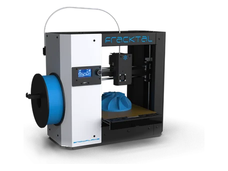
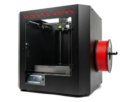
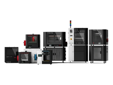
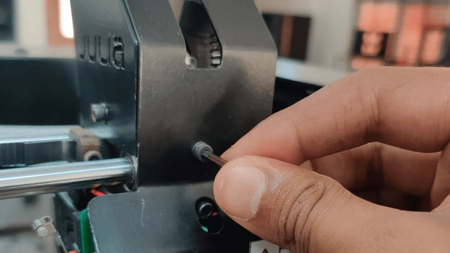
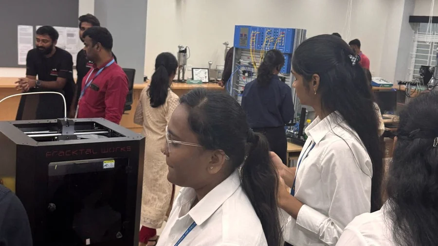
Every robotics lab we have visited has a desktop printer running most of the day. Chassis plates, servo brackets, sensor mounts and the tenth revision of a gripper are what it prints. The Julia was built for that kind of shared use, with a camera and a web interface so an overnight print can be checked and cancelled from a phone, and the Snowflake covers the same ground for a smaller budget.
Sending us a robot part
The parts on our robotics parts page are the shapes we see most. For anything else, send the file through the quote page with a line about what it holds, how much it weighs, and what it bolts to. An engineer checks the geometry and the orientation before anything is printed, which is the step that turns a part that should work into one that does.