










3D Printed Jigs, Fixtures and Gauges: A Design Guide

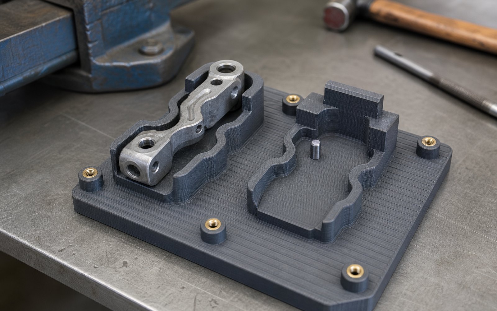
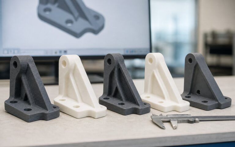
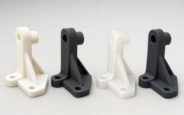
3D printed jigs and fixtures are the highest-return part anyone prints. A fixture is needed in ones, changes constantly, and is used hard, and every one of those properties makes machining it expensive and printing it obvious. This guide is what we have learned making them: which tooling to print, which material, how to design it so it holds a dimension, and when to stop and machine it after all.
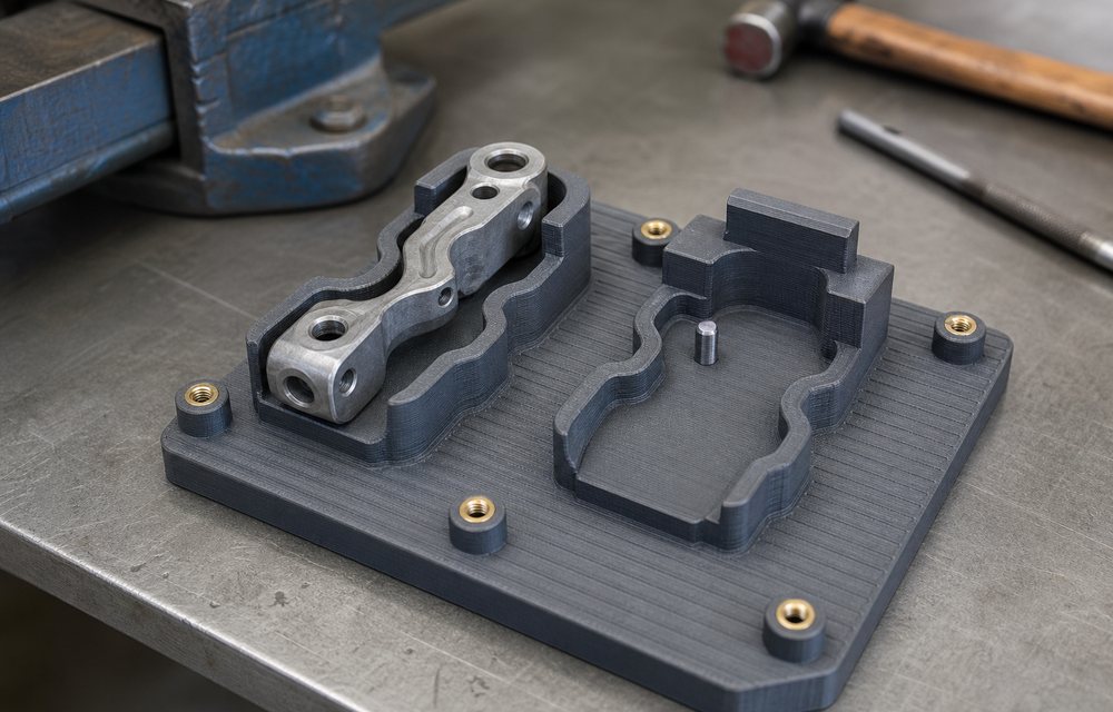
Jig, fixture, gauge: what each one does
The words get used loosely, and the design rules differ, so it is worth being precise.
- A jig guides a tool: a drill jig locates the drill, a soldering jig positions the iron, a marking jig positions the stamp. Accuracy lives in the jig, not in the operator.
- A fixture holds the work: an assembly fixture locates parts while they are fastened, a machining fixture holds a part against the cutting forces, a test fixture holds a product against its probes.
- A gauge checks a dimension without measuring it: go/no-go for a hole, a gap, a flush, a thread’s presence, a profile.
All three are custom to one part and one operation, made once or in small numbers, and revised as the process changes. That is the profile of a printed part.
Materials by job
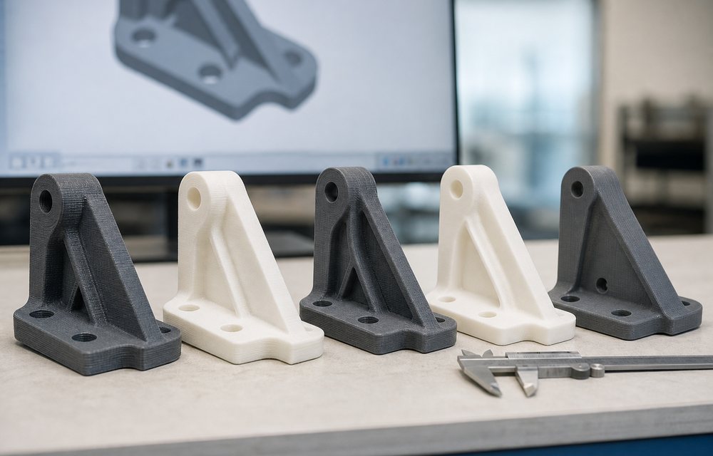
- PETG for most jigs and assembly fixtures: tough, cheap, easy to print, and it does not mark the product.
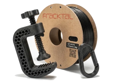
- Carbon-fibre PETG where the fixture must hold a dimension under a clamping load, or where it is long and must not flex.
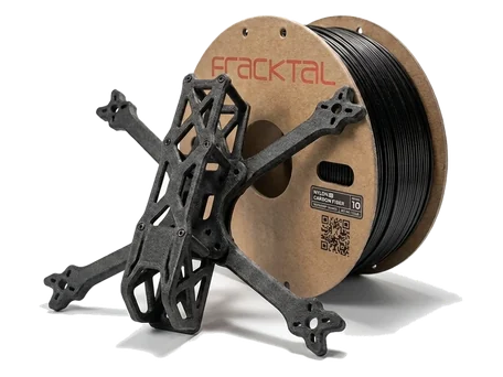
- Carbon-fibre nylon for fixtures that see heat, load and repeated use, and for anything on a robot.
- Nylon for guides and wear surfaces on jigs that see thousands of cycles.
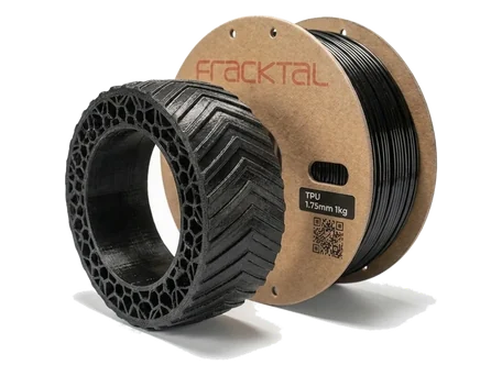
- TPU for soft jaws, pads and nests that must hold a finished surface without marking it.
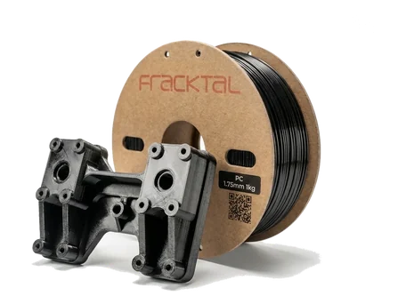
- Polycarbonate for fixtures near heat: potting, curing, soldering.
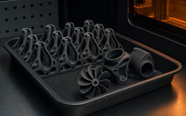
- Nylon 12 by SLS for gauges, where the uniform surface and freedom from support marks give a clean checking face, and for tooling wanted in tens.
PLA is for the first fit-check of a fixture design and nothing after: it creeps under sustained clamping load and softens in a warm shop.
Design rules that make printed tooling hold
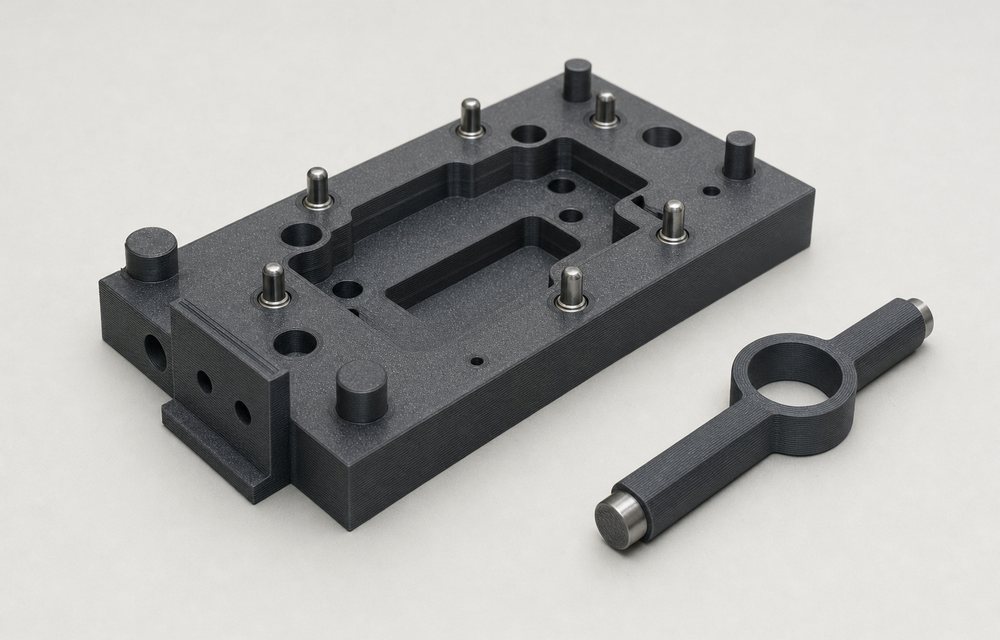
- Locate on three points, clamp on the fourth. The same rule as machined tooling. Printed fixtures that try to locate on a whole surface rock on the layer texture.
- Metal where metal is needed. Dowel pins for location, heat-set inserts for every thread, a steel bush in a drill jig, a hardened pin for any go/no-go face that sees a tool. Printed plastic is the body of the tool; the wear and the precision are in metal.
- Orient the layers against the load. A clamp arm that bends about its root should be printed with the layers along it. Where a load has to cross the layers, add a fillet and thicken the section.
- Walls and ribs, not solid blocks. A fixture body at 2.5 mm walls with ribs is stiffer per gram and prints in half the time of a solid one. Solid printed blocks also warp.
- Clearance on the part. 0.2 to 0.3 mm on FDM around a located part; more where the part has its own tolerance. Holes print undersize, so ream any hole that locates.
- Design the reference into the fixture. A printed datum face, machined flat afterwards, gives a fixture a true reference for a few minutes of work.
- Label it. Emboss the part number, revision and orientation arrow into the fixture. A printed fixture without a label is the one that gets used on the wrong variant.
Our design for 3D printing page has the dimensions per process.
Gauges: the case where SLS wins
A gauge is used hundreds of times a shift and its face must not wear or mark. SLS nylon gives a dense, uniform checking face without support scars, and a set of gauges for a whole product family prints in one build. Where the face sees a hard part, press in a hardened steel insert. Calibrate a printed gauge like any other: check it against a master and record it.
When to machine it instead
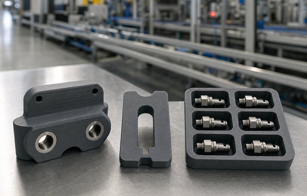
Printed tooling has limits, and knowing them keeps the credibility of the ones that work. Machine the tool when it carries heavy machining forces, when the tolerance on the located feature is tighter than ±0.1 mm without metal inserts to carry it, when it sees continuous heat above the polymer’s deflection temperature, or when it will be used unchanged for years at high volume. The printed version is often still the right first step: prove the design, then machine the final one from the validated CAD.
Cost and lead time
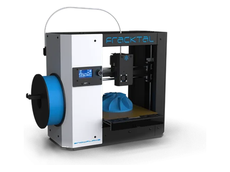
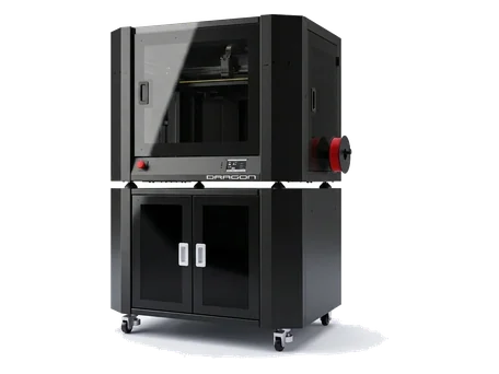
A printed fixture typically costs a tenth to a third of the machined one and is ready in one to three days. The larger saving is the one nobody bills: a fixture that is redesigned five times because redesign is cheap ends up better than one that was designed once because redesign was expensive. Plants that print tooling in-house on a Snowflake or Julia keep that loop on the shop floor; the long guides and large fixtures come to our Dragon or the manufacturing floor.
Getting a fixture made
Send the CAD of the part the fixture holds, a sketch or a description of the operation, and the loads involved, through the quote page. If you would rather we designed the fixture, our design services do that, and the jigs and fixtures page shows the shapes we make most.