











3D Printed End-Use Parts: When Production Printing Pays

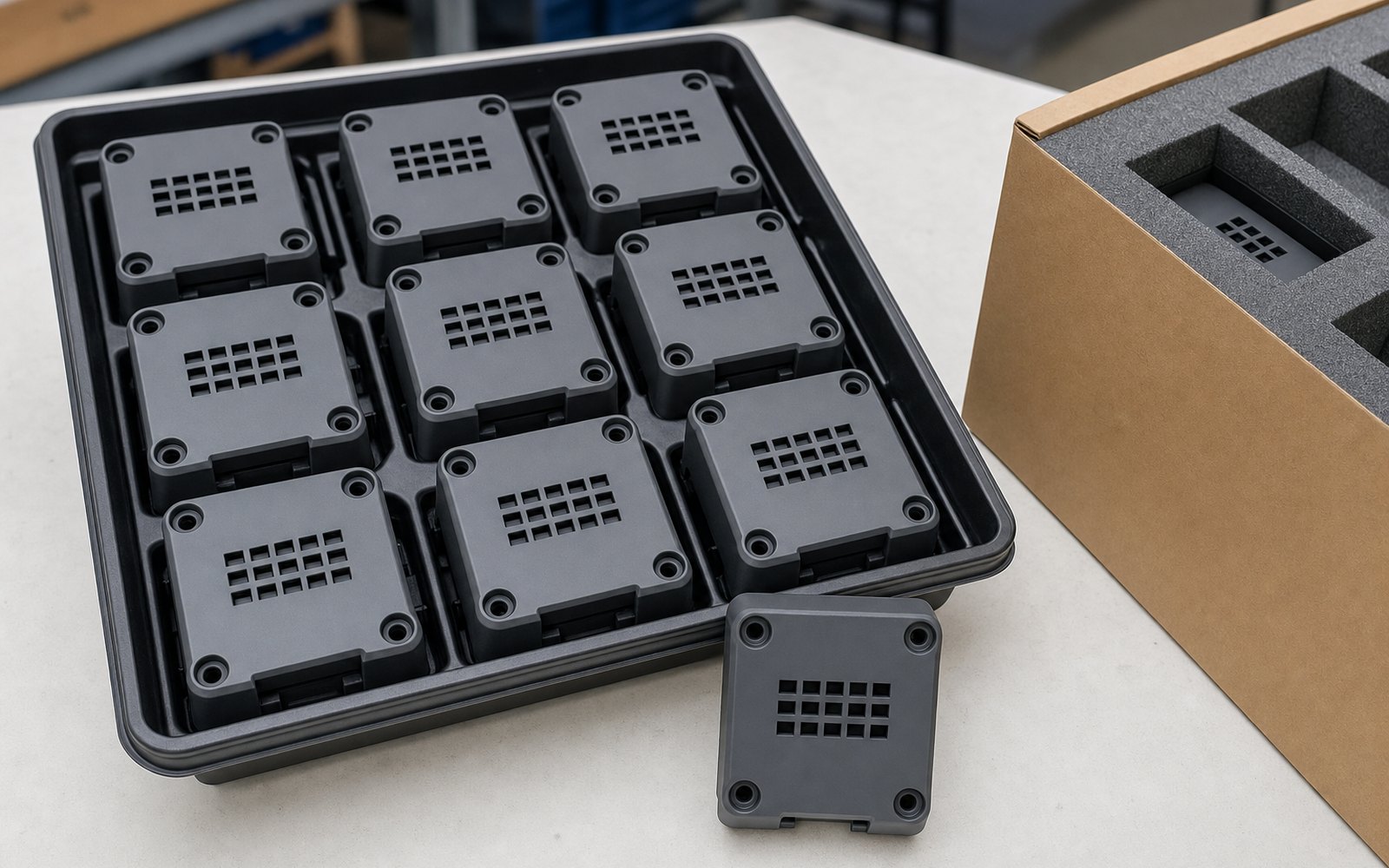
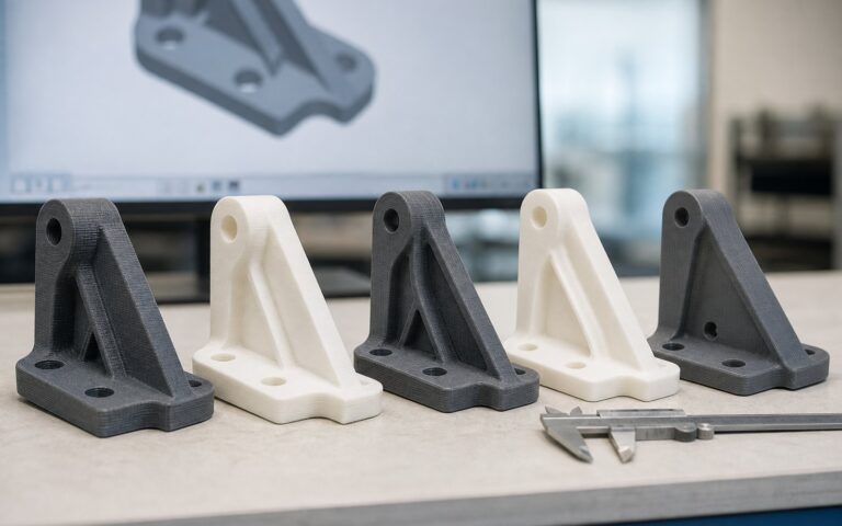
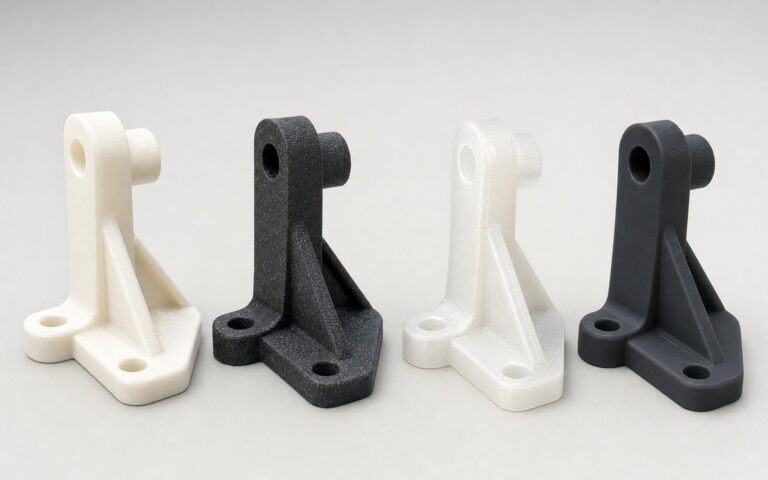
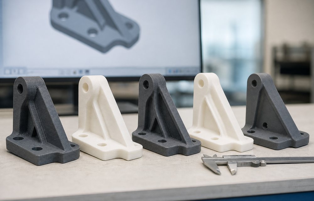
3D printed end-use parts are production parts made without a tool: the housing, the clip, the duct or the bracket that ships in the product, printed rather than moulded. It makes sense in a narrow, well-defined band of quantity and design, and outside that band it is the wrong choice. This article draws the band, with the processes, materials and the arithmetic, so you can tell before you upload a file which side of it your part is on.
The quantity band
An injection tool costs a fixed sum and then makes parts for very little each. Printing costs nothing to set up and then costs about the same for every part. The two lines cross at a quantity that depends on the part, and that crossing is the whole economics.
- 1 to 50 a year: printing wins outright. FDM for the widest material range; SLS for nylon parts without support marks.
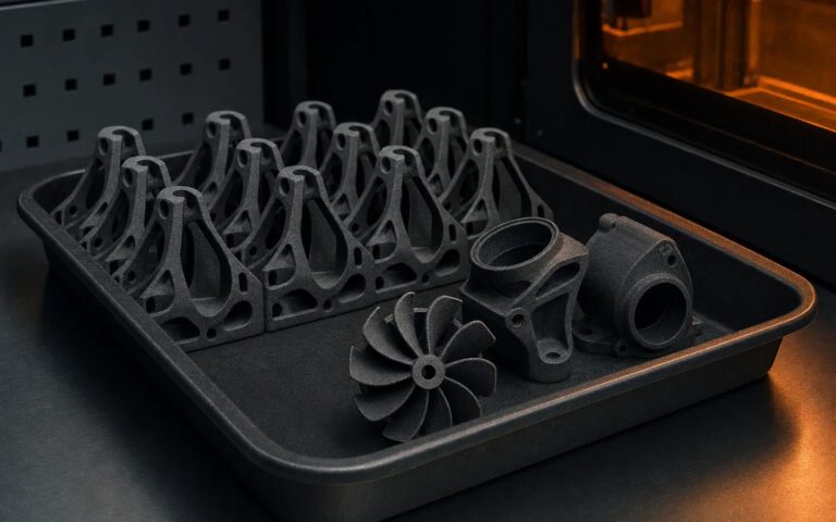
- 50 to a few hundred: SLS or MJF nylon, where a full bed prints at once and the per-part price falls hard. This is the band where most end-use printing lives.
- A few hundred to a few thousand: it depends on the part. Small, simple parts tip towards moulding early; large, complex or frequently changed parts stay printed for longer. Vacuum casting covers parts that must look moulded in this band.
- Thousands and up: injection moulding, and the printed parts were the pilot run that validated the design before the tool was cut.
The design band
Quantity is half of it. The part’s shape decides the other half.
- Complexity is free. Internal channels, undercuts, lattices, consolidated assemblies: features that make a mould expensive or impossible cost nothing to print. A part with these is printed further up the quantity scale.
- Size costs. Printing time scales with volume. Large, chunky parts are expensive to print and cheap to mould; small, intricate parts are the reverse.
- Change is cheap. A part that is revised every quarter never earns back a tool. Printed parts are revised by editing the file.
- Variants are free. Ten variants of a bracket are ten files, not ten tools.
Processes for production parts
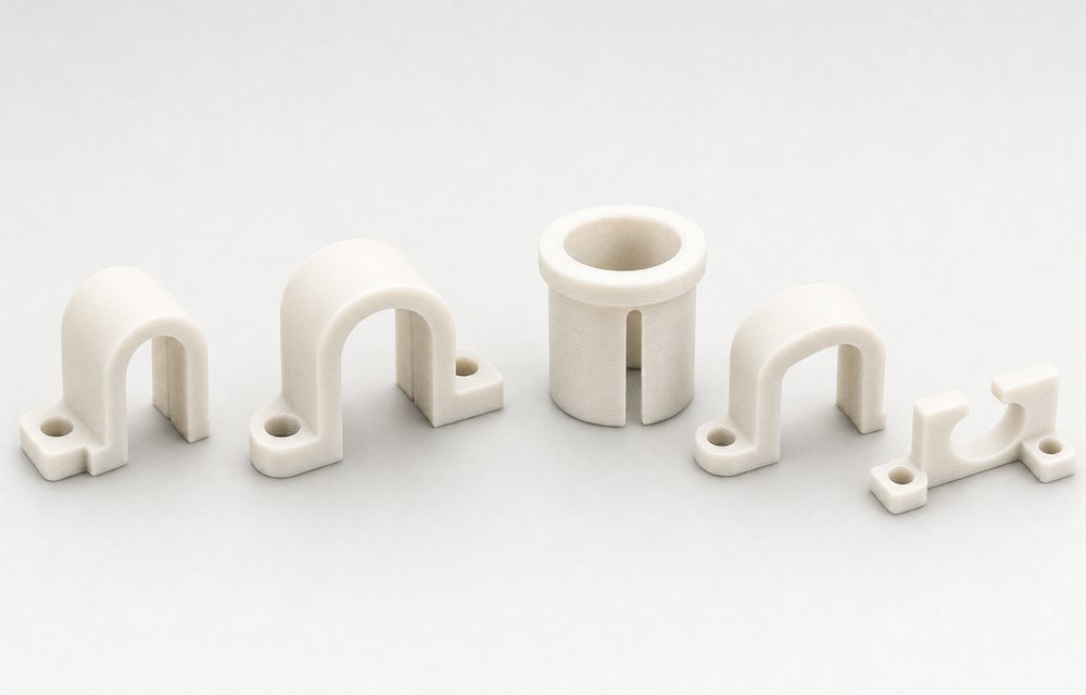
- SLS nylon 12 is the default production process: tough, consistent in every direction, a uniform matt surface, no supports, and fifty parts in one build. Living hinges, snap-fits and clips work in it.
- MJF nylon 12 is its faster sibling for batches in the hundreds, with a slightly smoother surface. Our SLS vs MJF comparison sets out the differences.
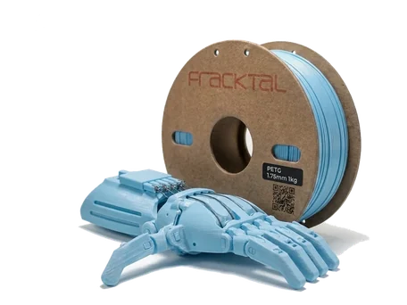
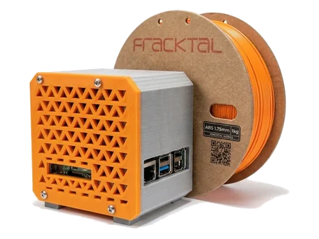
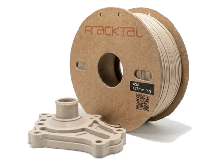
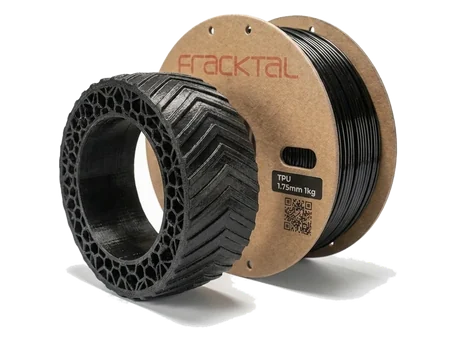
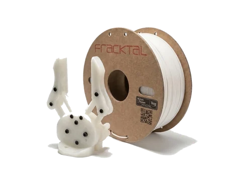
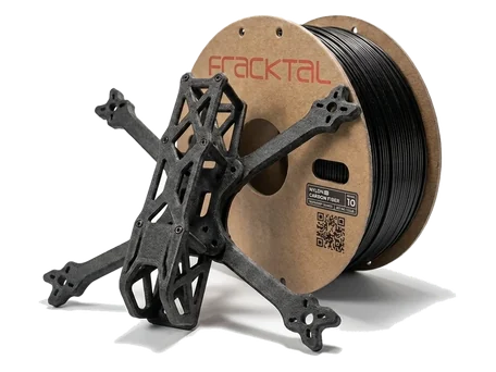
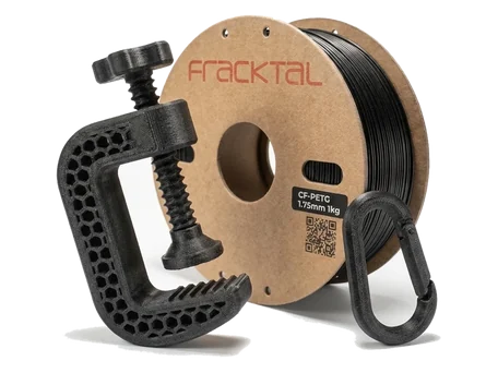
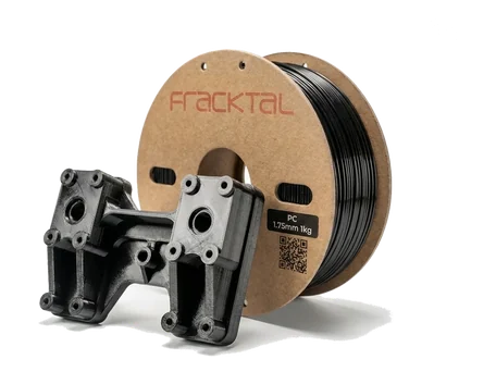
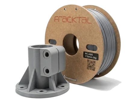
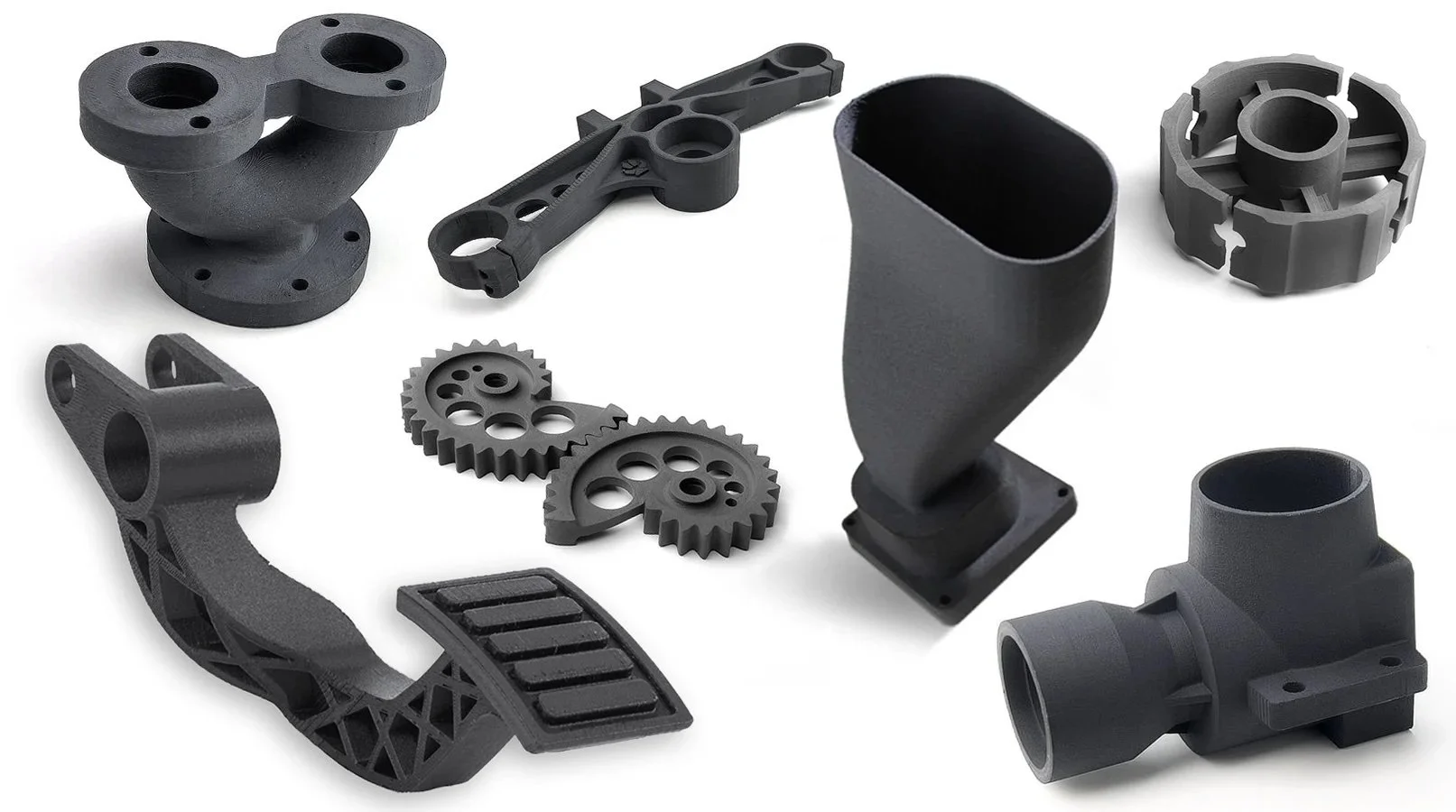
- FDM in engineering polymers when the part needs a specific material: polycarbonate for heat and impact, ASA outdoors, carbon-fibre nylon for stiffness, TPU for flexible parts. Printed on heated-chamber machines so a batch does not warp.
- Vacuum casting from a printed master for 15 to 25 parts per tool in polyurethane, when the finish and colour have to match a moulded product.
Finish and consistency
A production part has to look and measure the same every time. SLS and MJF parts are bead-blasted as standard and can be dyed black or coloured; FDM parts get support removal and light finishing, or vapour smoothing on ABS and ASA for a glossy surface. The finishing and assembly page shows each. On the measurement side, every batch is checked against the drawing before dispatch, and the quality assurance page describes what is measured and what the report contains.
A part that has been in service
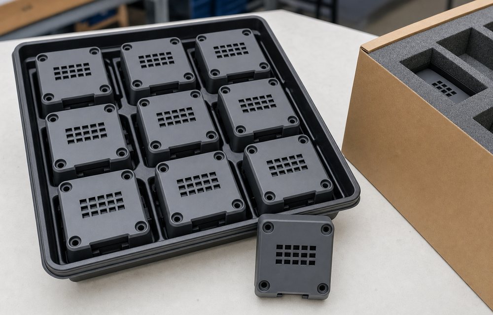
One of the first production parts we printed was a component for AUMA’s induction motors, a part that had been stocked as a physical spare and is now printed when it is needed. It is a small case, and it is typical: not a headline, a bracket that works, made to a file rather than held on a shelf. The spare parts article covers the inventory that grows from parts like it.
Design rules for a part that ships
- Wall thickness of 1.0 mm minimum in SLS (0.7 mm is printable, 1.0 mm survives handling), 1.2 mm in FDM, 2 mm where a fastener bites.
- Clearance of 0.5 mm between moving surfaces in SLS, 0.2 to 0.3 mm on FDM mating parts.
- Drain holes of 5 mm or more on any enclosed volume in SLS, so the powder can be removed.
- Orientation decided with the engineer, because it sets the surface, the strength and the price.
- A drawing with tolerances on the features that matter, and a material called out by grade, exactly as for a moulded part.
The fuller list is on the design for 3D printing page.
Deciding for your part
If the part is needed in fewer than a few hundred a year, changes, has variants, or has geometry a mould would struggle with, it is probably a printed part. Send it through the quote page with the annual quantity and the drawing, and we will quote the printed part and say plainly if a tool would be cheaper. The end-use parts page has examples across the band.